Creation of Column Schedule and Drawing Template using AutoCad
1.
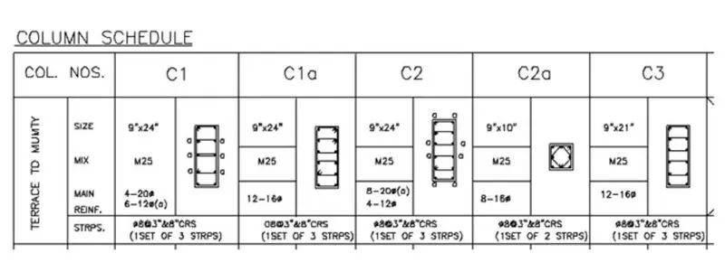
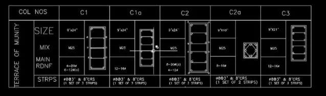
Aim: To create a column schedule as given in the figure
Procedure:
- Open AutoCad.
- Set the units, Engineering with precision 0'0.0"
- Set the limits.
- Now using the LINE, draw a 9" horizontal line and 24" vertical line on both sides
- Using OFFSET command, draw an offset of 0.6" on all the four sides.
- Using TRIM command, trim all the unwanted lines.
- Now type DDPTYPE and select suitable point types
- Using DIVIDE command, divide the line into 5 segments on 24"of both sides
- Now using TEXT command, select a single line text of height 8" and 90 angle, and type TERRACE OF MUNITY in it
- Using the TEXT command, select a single line text of height 8" angle 0 angle and type COL NOS, SIZE, MIX, MAIN RDNF and STRIPS
- Using CIRCLE command, a circle of diameter 20mm of 4 number at suitable point is made.
- Using CIRCLE command, a circle of diameter 20mm of 6 number at suitable place is made.
- Using FILLET coomad, a radius of 9mm at 4 corners is made.
- Now Using TEXT command, making a height of 8: and style Roman.shx and an angle of 0 degree and type 9"*24", M25,4 20 dia
- Use LWEIGHT command, and draw stirups of 8mm dia at the required places
- Using SCALE command, scale the texts and diagram
- Using LINE command, draw a line like table and place the texts and diagram in suitable places.
RESULT:
2.
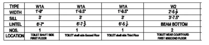
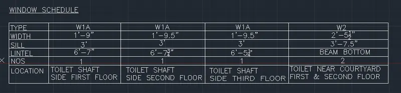
Aim: To create a window schedule as shown in the figure
Procedure:
- Open AutoCad and select new and imperial system
- Select Architectural with precision 0-0 1/256"
- Using TABLE command without title and header, draw table with 5 columns and 6 rows with column width 2 1/2" and row height 1.
- Using TEXT command, enter the required data at the required columns and rows.
RESULT:
3.
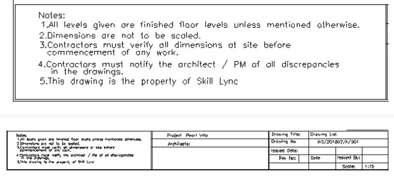
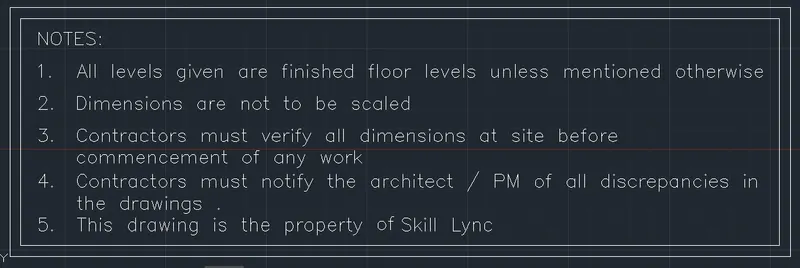
Aim: To create the drawing template as given in the figure
Procedure:
- Open AutoCad.
- Set the units, Engineering with precision 0'0.0"
- Set the limits.
- Using LINE command, tables are made.
- Using ST command in command prompt, select multiline text, Roman.shx font is selected with height 8"
- Now type the required data in the table made.
Result:

4.
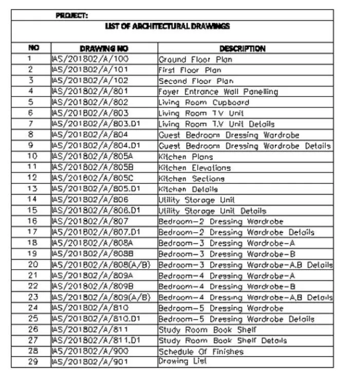
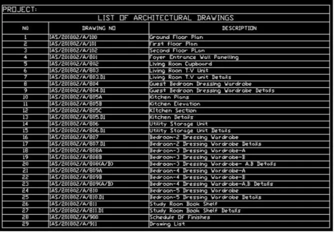
Aim: To create the list of drawing schedule as shown in the figure
Procedure:
- Open AutoCad, select new drawing using QNEW, and imperial system
- Open Annotate table and select standard
- Using TABLE command, make 2 tile and header with 3 columns with column width 2.5" and 30 rows with row height 1
- Using TEXT command, Type PROJECT and justify left
- Using TEXT command, type LIST OF ARCHITECTURAL DRAWINGS and justify center
- Now relevant details are entered in the appropriate rows and colums, using TEXT command.
Result:
5.
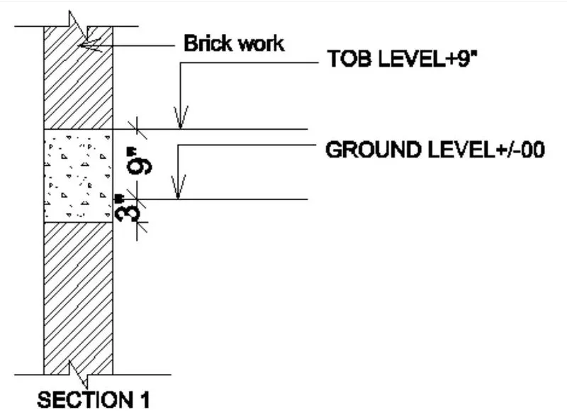
Aim: To create the Beam detail as shown in the figure
Procedure:
- Open AutoCad, select new using QNEW and Imperial system.
- Select Engineering with precision 0'0"
- Using LINE command, draw vertical line with 12"
- Using OFFSET command, offset 2" to that vertical line
- Select the BREAK-LINE symbol in the express tool tab and specify the two points to break the line on both sides
- Using HATCH command, slect AR CONC, and select the concrete portion to hatch and scale to 0.05
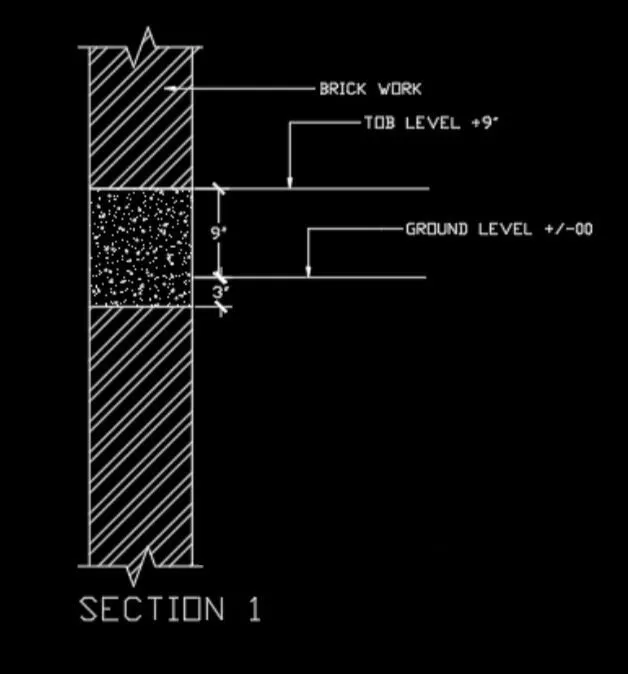
- Select multileader style manager and modify in leader structure and make 2 as maximum leader points and type BRICK WORK
- Select multileader style manager and modify in leader structure and make 3 as maximum leader points and type TOPLEVEL+9" and GROUND LEVEL +/-00
- Select Manage dimension style from the Annotate tab and in symbols and arrows, change the arrowheads to Architectural tick
- Using DIMLINEAR, dimension the concrete portion and using TEXT command with 0 angle , type SECTION 1.
RESULT: