Creation of Column Schedule and Drawing Template using AutoCad
1. Create a column schedule as shown in the figure.
Note: Create a column schedule with the help of lines. Also, insert text with the help of Dtext command or Single Line text.
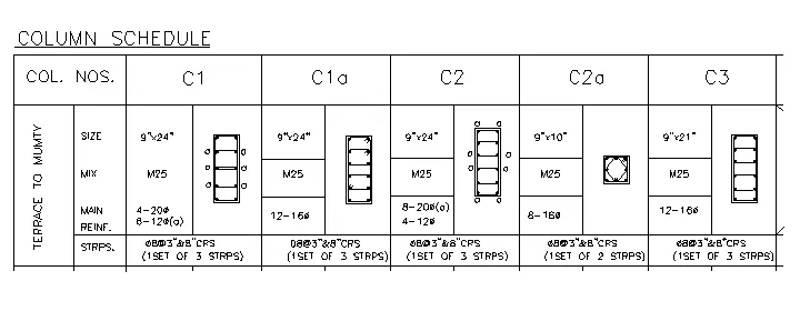
AIM: To create a column schedule as shown in the figure using AutoCAD
PROCEDURE:
Open a new drawing template and type in UNITS and give the required type and scale.
Type as Architectural and Precision as 0-0 1/256" and apply
Select the Line command from the ribbon tab or press L for the line.
Draw the tables using the line command in the required dimensions
Use command Trim to delete the unrequired lines from the table
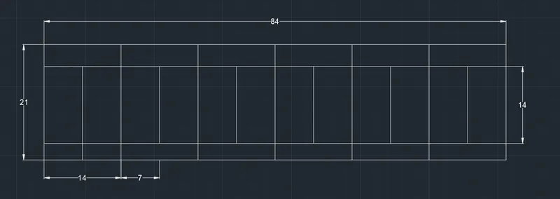
Using the circle and line commands draw the columns.
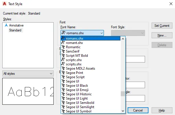
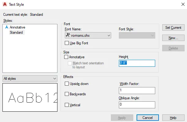
In the text style dialog box select the font as romans.shx and height as 8".
Right-click on the text and select properties and give the angle as 90 for the required text and the rest to 0.
Type in all the text in the required columns.

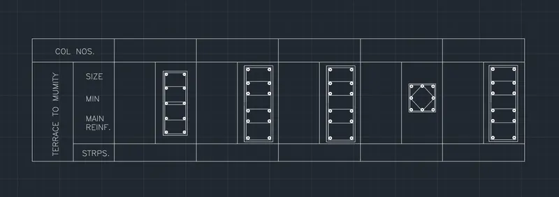
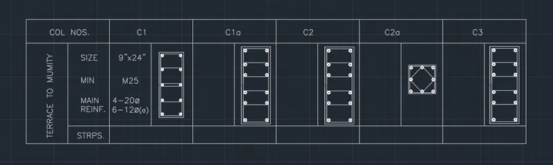
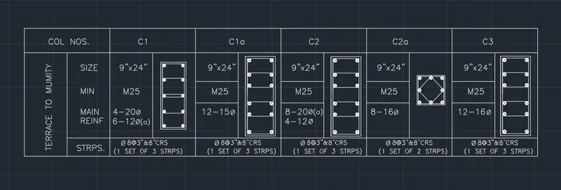
2. Create a window schedule as shown in the figures:
Window Schedule:
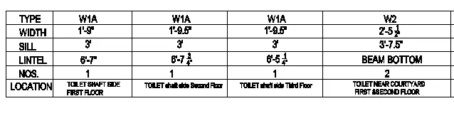
AIM: To create a window schedule.
PROCEDURE:
Open a new drawing template and type in UNITS and give the required type and scale.
Type as Architectural and Precision as 0-0 1/256" and apply
Select the Line command from the ribbon tab or press L for the line.
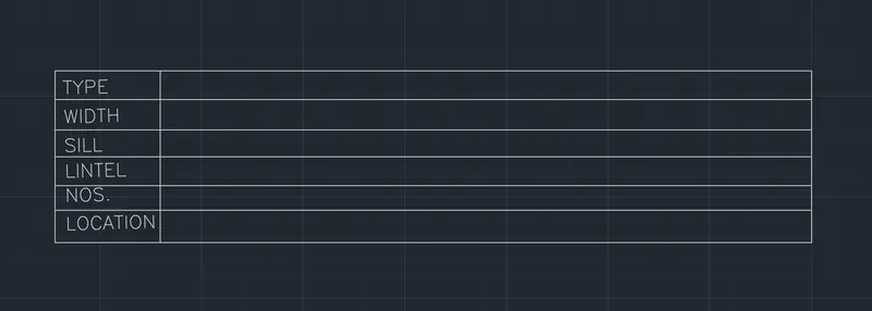
Using a single line from the Ribbon tab or Dtext command to write the texts.
Type the required text on the table
Adjust the size of the text in the lower column to 6"
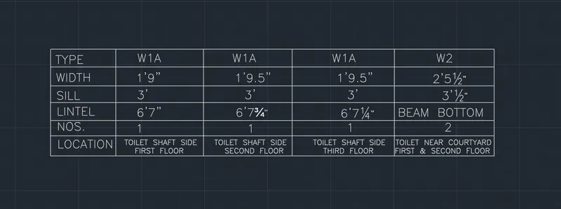
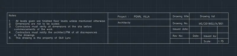
3. Create the drawing template as shown in the figure:< Use the Notes as in the figure>
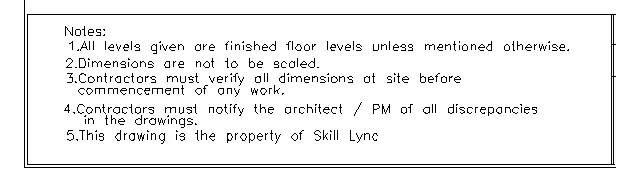

Aim: To Create a window schedule in AutoCAD
Introduction: Templates are stencils that allow you to draw specific symbols and shapes that you use repeatedly in a design.
To create this template Line, Trim, Text, and Multitext commands are used.
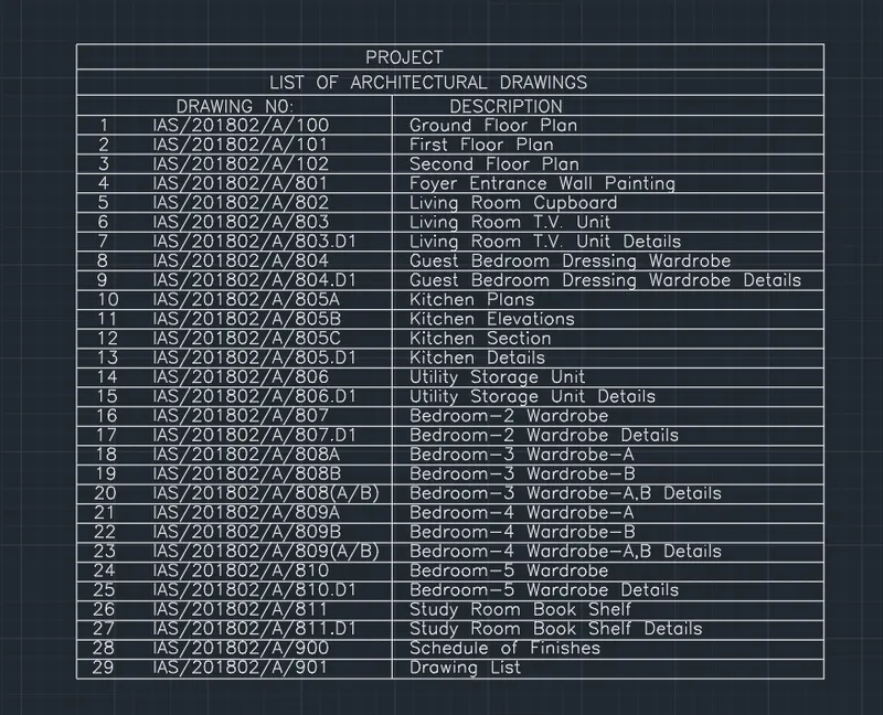
4. Create the list of drawing schedule as shown in the figure:
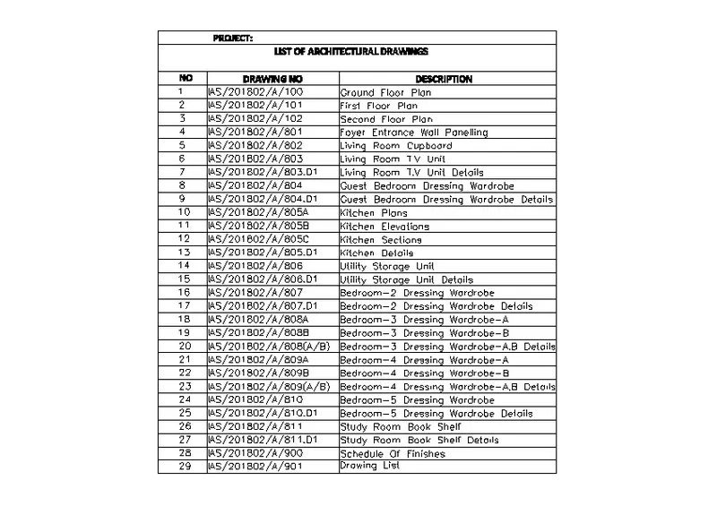
Aim: To create the list of drawing schedules as shown in the figure.
Procedure:
Type "units" in the command prompt and press enter.
Select the units as "Architectural" and click ok.
Draw the lines in the required spacing
Select single line text or Dtext and type in the required text and press Enter
Then move the headers to the correct positions
Close the table in the end
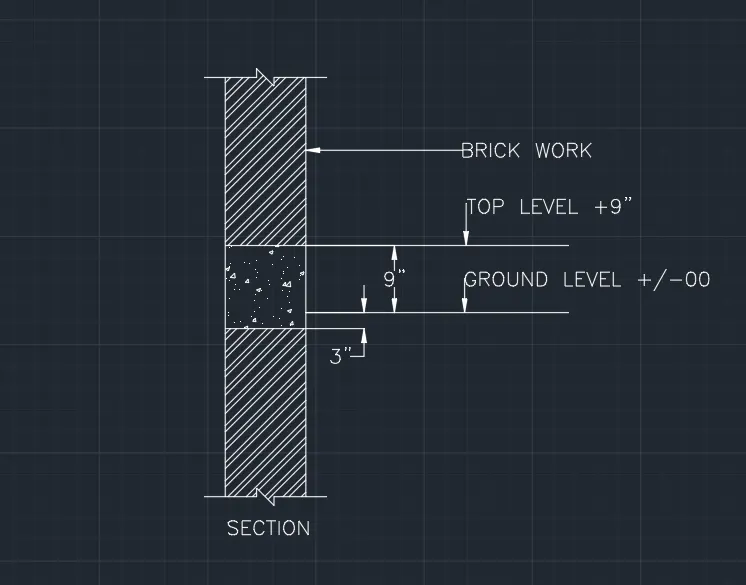
5. Create the Beam detail as shown in the figure and provide text wherever given.
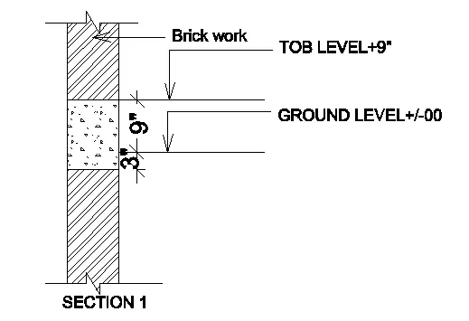
AIM: Create the Beam detail as shown in the figure and provide text for the Top level and Ground level wherever given.
PROCEDURE:
Select the line command from the ribbon tab.
Draw the lines for the beam then for the top section draw and trim the lines
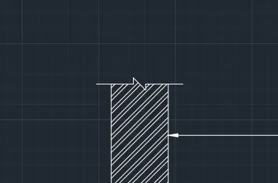
Use the hatch command and give the hatches to the layers
Give dimensions and mark the details.