Creation of Column Schedule and Drawing Template using AutoCad
AIM:
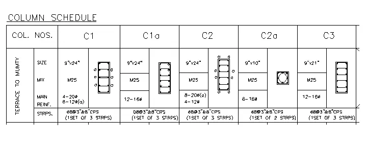
Create a column schedule as shown in the figure.
Note: Create a column schedule with the help of lines. Also, insert text with the help of Dtext command or Single Line text.
INTRODUCTION:
- Giving the details about required Structual deatils of the columns with using the multiline text and line command to form tables
PROCEDURE:
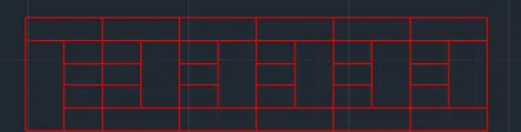
- Draw the table by using line command L enter as we required
- Use the layer properties and add an layer with table is red in colour and enter and drawn the table as shown in the below drawing
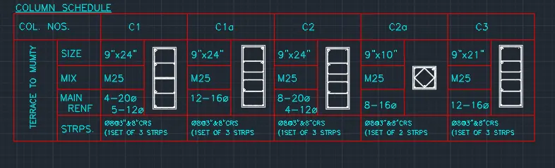
- Use the multiline command use the text height is 9" with justify is left and text font is romans and enter the required text
- After the text was entered draw the required sizes as columns with rebars assual to mention the deatils of the columns
RESULT:
AIM:
2.
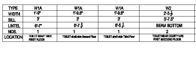
Create a window schedule as shown in the figures:
Window Schedule:
INTRODUCTION
- To give a details about the windows for first floor second floor and third floor with use the single linte text and line command for table
PROCEDURE
- Use the cable command by using TABLE enter
- Select the properties as 6 columns abd 5Rows and enter as shown in figure
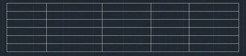
- Select the table properties and select the test height id 8"and enter
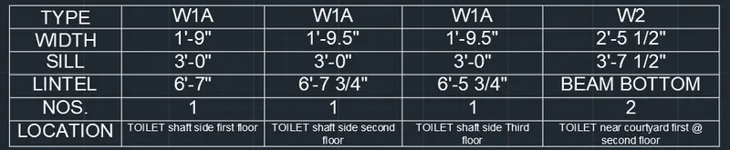
- And enter the required data with text height is 8"
RESULT:
AIM:
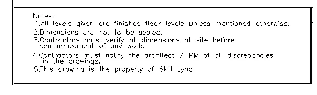
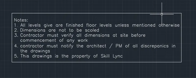
Create the drawing template as shown in the figure:< Use the Notes as in the figure>

INTRODUCTION:
- The write the details about the project details with the note
PROCEDURE:
- Open the new drawing templete
- and change the units to enginering and inches and enter
- use the text as multiline test and enter
- Draw a rectangle withe the multiline command and enter the test with 9" and text font is romans and enter the text as shown in below drawung
- Create the table with the help of Line command create the required table as shown in below drawing

- Enter the required text on the table and enter
Result

AIM:
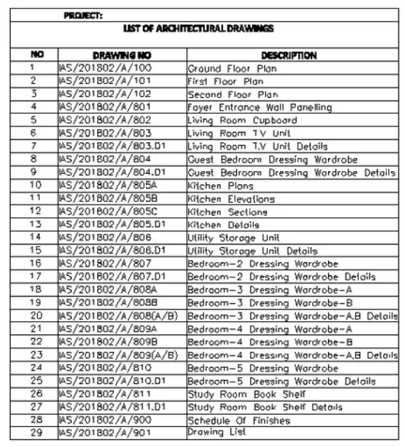
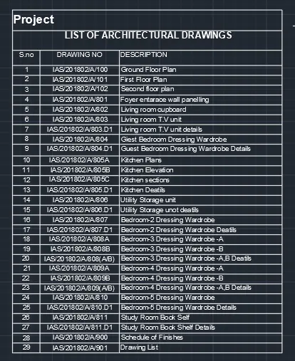
4. Create the list of drawing schedule as shown in the figure:
INTRODUCTION
- To give the complete details about the list of architectural drawings with details were given in the below table
PROCEDURE:
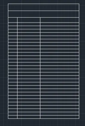
- Use the cable command by using TABLE enter
- And select the default table and enter
- And ad the required rous by chossing the insert rows and columns and enter
- And merge the 1 and 2 row by secting merge in rows and enter
- after doing all the the table was created as shown in fig
- And Enter the Reqired data by selecting the table
- Project text height is 8"
- List of architectural drawings height is 6"
- Remaing details height is 4.5"
RESULT
AIM
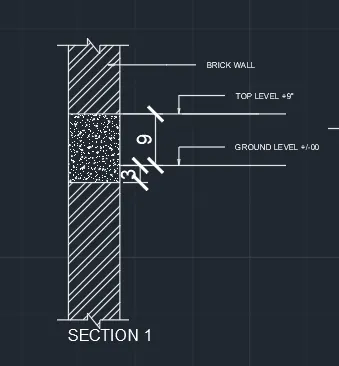
5. Create the Beam detail as shown in the figure and provide text wherever given.
INTODUCTION
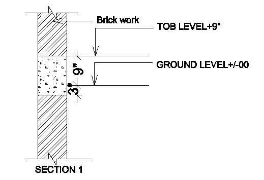
- To draw a diagram for the section 1 for giving the top level and ground level with the brick wall
Procedue
- Use the line command by using L enter
- Draw a line with 4' and enter towards N Direction
- And use the offset command by using O enter and do offset to the 4' line towards E direction and enter
- And use the line command and draw a sections line on both sides top and bottom and enter
- Use the line command and draw a line And select the mid point of the 4' line and draw a line towards E direction with 9"
- And use the offset command and do offset command towards N side with a distance of 1' and enter
- Draw a line Top level with 9" towards E direction
- And do offset to the line with 9" towards bottom side and enter as shown in fig
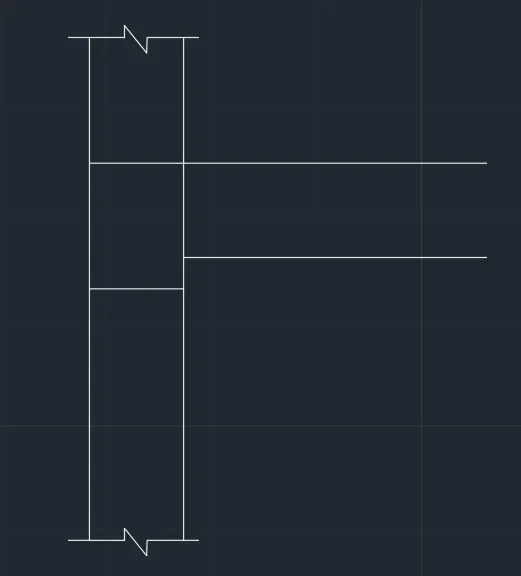
- Use the dimensiona and hatch and text to the drawing
RESULT: