Creation of Column Schedule and Drawing Template using AutoCad
AIM:
The aim is to create a column schedule and drawing template using AutoCAD with the help of the model given.
INTRODUCTION:
Fillet - It is a tool used in AutoCAD to create a rounded edge between two lines that may or may not be intersecting. It can be selected from the modify ribbon or by typing fillet on the command bar.
Trim - It is a tool used in AutoCAD to remove the excess lines or parts of object without entirely removing the object or the line. It is one of the most commonly used tools in AutoCAD.
Rotate - This tool is used to rotate the selected object or line in the specified direction. This can be selected from the ribbon with the rotate icon or by typing rotate in the command box.
Text - Text tool is used to enter text in the AutoCAD file. It has single line text and multiline text. The text entered can also be edited in the AutoCAD.
Copy - It is a modification tool used in AutoCAD that is used to copy a single object into more number of objects. For doing this, first, the object has to be selected. Then the base point has to be selected. After that, the new location has to be selected in which the object has to be copied.
Move - It is a modification tool used in AutoCAD that is used to move an object from the current location to another location. For doing this, first, the object has to be selected. Then the base point has to be selected. After that, the new location has to be selected in which the object has to be moved.
Offset - It is a modification tool used in AutoCAD that is used to create multiple objects inwards or outwards of the current object or from a equal distance from the original position.
PROCEDURE:
Figure - 1
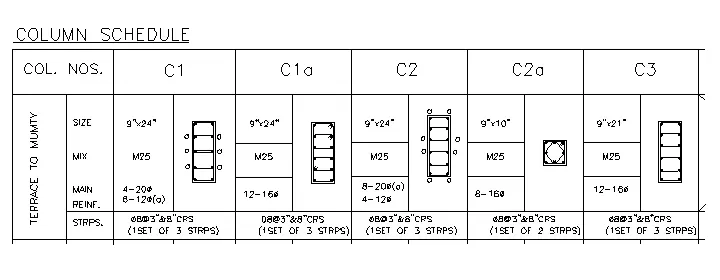
- First, using the line command table is drawn as per given in the question.
- The commands like copy, offset, extend, fillet and trim was used to complete the table.
- Line command was used to draw the first two columns of the table.
- While drawing the first two columns of the table, offset was used to make the columns equally spaced.
- Once the second column was drawn, then copy tool was used to make multiple copies of the second column to complete the table.
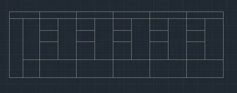
- Once the table was completed, text were entered using the text command.
- Both single line text and multiline text were used to enter text.
- The text entered has a text height of 8" and the font used was romans.shx
- If there are same text to be used in multiple places, copy tool was used to paste them in the respective places.
- If the space provided to enter text is not sufficient, then the size of the table was adjusted to make space for the text.
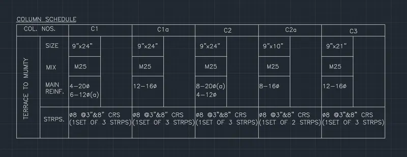
- In the places provide for the column cross section, the column cross section was placed which is drawn using line command, rectangle command, fillet tool, circle tool, mirror tool, array tool and text tool also.
- The dimension was taken from the table for completing the cross section of the column.
- Once the cross section was drawn then it is scaled down to fit inside the space provided. Then it is moved into its place.
- Like this all four column cross sections were drawn.
RESULT:
The given figure is drawn and is shown below.
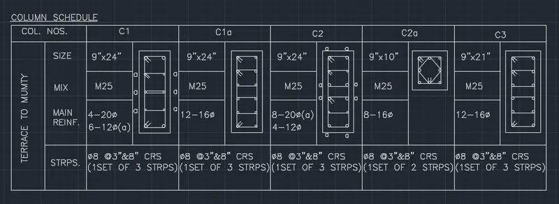
Figure - 2
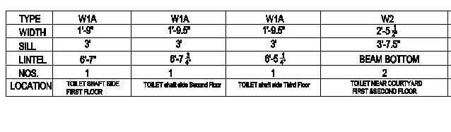
- The first step is to create a table with 5 columns and 6 rows.
- The table can be selected from the annotation section in home tab.
- Then the text were entered in the respective cells.
RESULT:
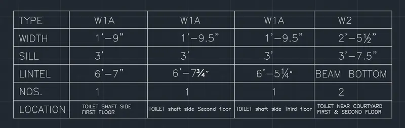
Figure - 3

- First step is to create a rectangle using the rectangle command.
- Then multiline text command is used and the text needed to be entered is typed.
- After that numbering command is applied to the needed points.
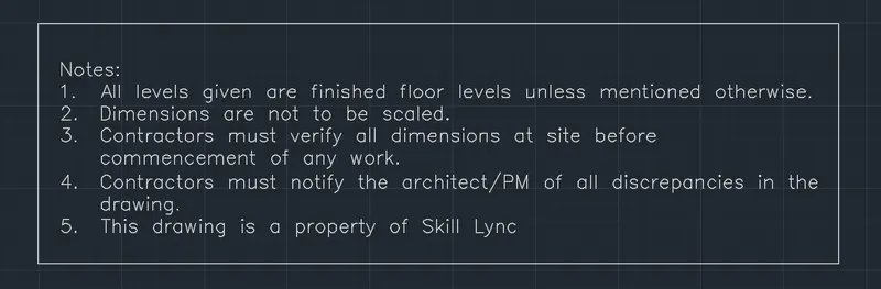
- Then lines are extended from the rectangle horizontally to enter the project details and architect details.
- Using the text command, the text is typed in the respective places.
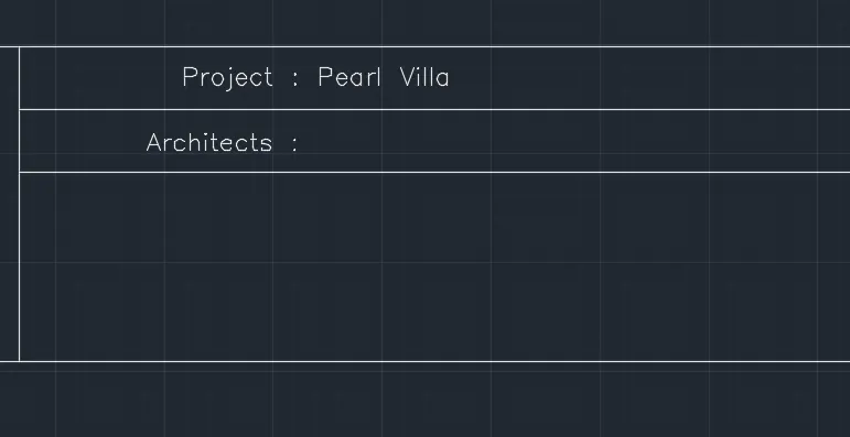
- Using lines a table is created with 5 rows and columns as needed
- Then using text command, the required text is filled in the spaces.
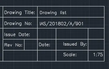
RESULT:
The given figure is drawn and is shown below.
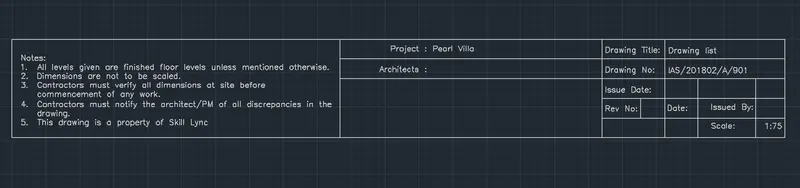
Figure - 4
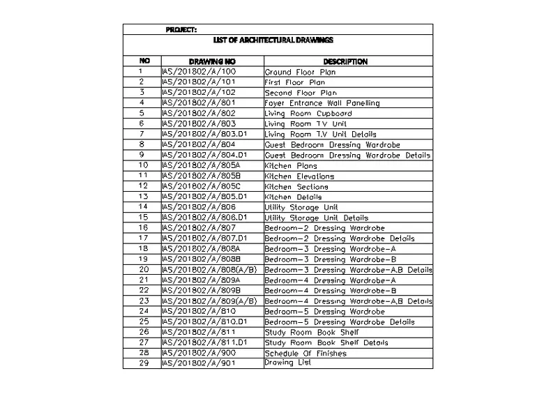
- The line command is used to draw a table with 32 rows and 3 columns.
- The offset tool was used to draw the table using lines.
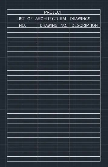
- Then the text needed to be entered is typed with the help of the text command.
- The text size and style can also be edited using the text editor section that comes when editing a text.
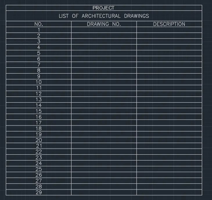
RESULT:
The given figure is drawn and is shown below.
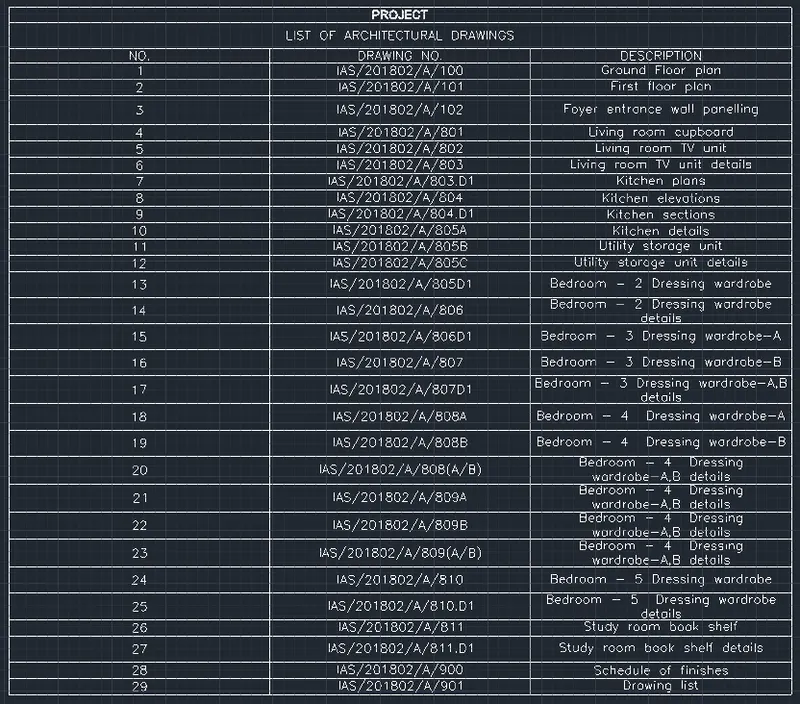
Figure - 5
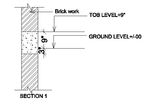
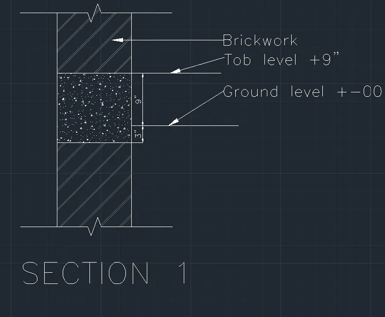
- Line command is used to draw two parallel lines.
- Then line break symbol is placed on the two ends of it.
- Two more lines are added in between the two lines.
- Then hatch is applied in the needed places. Two types of hatches were used here,the concrete hatch and a diagonal line hatch.
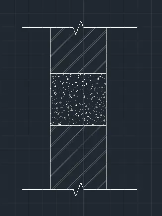
- The dimensions of the line is marked and then headers were provided marking the brickwork and the ground and top level.
- Also the section is named as Section 1 using the text command.
RESULT:
The given figure is drawn and is shown below.