Creation of Column Schedule and Drawing Template using AutoCad
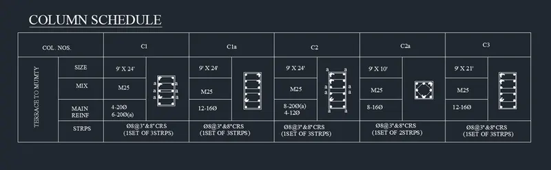
1. COLUMN SCHEDULE:
Aim: To prepare column schedule.
Procedure:
- First we create a table by drawing a rectangle of 60'X20' and then explode it.
- By using offset command: offset the 20' line by taking offset at a distance of 5' and then offset the 60' line at a distance of 4' from bottom and 2' from top.
- Trim off the extra lines using trim command.
- Now we enter the text in the table by using singleline text from the text drop down menu.
- Specify the point of text,text height as 8" and text angle as 0 degree.
- After entering the text,right click and select properties then list of properties will be shown and ensure that the text height is 8" make justify as left.
- By using "ST" command we can change the style of the text and select the font name as "romans.shx".
- Insert all the text on the respective rows and columns.
- Give the heading as column schedule.
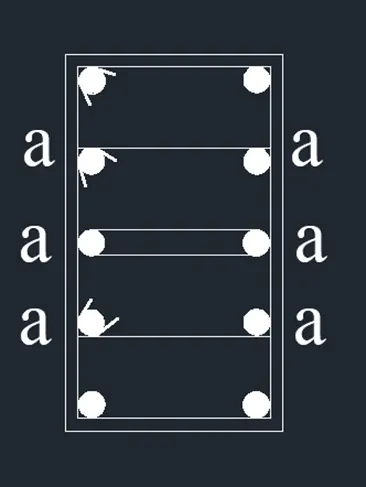
- Now we draw the column section:
a) For column C1 draw a rectangle of 9"X24" having 20mm dia reinforcement at 4 corners and 12 mm dia 6 reinforcement bars in between connected by 8mm dia stirrup.
- Now we draw a rectangle using the reactangle command using dimensions in the command box.
- By using offset command: give an offset distance of 0.5" which will be the cover of concrete.
- Explode the inner rectangle using explode command.
- Now we draw the reinforcements:
- By using the circle command: selecting tan tan radius circle and give the radius of 0.4".
- Using mirror command create the reinforcement on the bottom left side of column by giving plane as the midpoint of the 2' line and click on NO for erase source object.
- Now by using divide command: divide the 2' line into 4 segments.
- To make the points visible type"DDTYPE" in the command box and apply a suitable point.
- Now for the reinforcement of 12mm dia bars 6 in numbers.
- Create a circle of radius as 0.2" using circle command.
- Now copy the circle using the top of the circle as the base point and place it on the points created by object snap.
- Place all the 3 circles on the each divided point and then delete the points created.
- Create similar circles on the right side by using the mirror command.
- Now we draw the stirrups:
- Connect the reinforcement 6mm with 1st row and 2nd row from top and bottom and the 3rd row from the bottom.
- Connect them as tangents of two circles.
- Now fillet the corners of the column with radius as 0.5".
- Now using the donut command fill the circles.
- Specify the inner dia as 0 and outer dia as 0.8" for the corner reinforcement and 0.5" for the inside reinforcement.
- Specify the centre of donut and fill the circles.
- Mark "a" for in between reinforcement to indicate it as 12mm diameter.
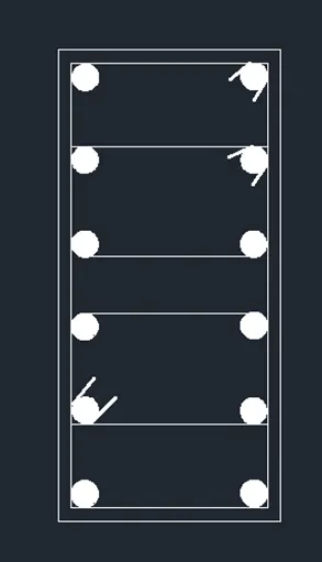
b) Now drawing column section C1a of size 9"X24" having 20mm dia reinforcement at 4 corners and 12 mm dia 6 reinforcement bars in between connected by 8mm dia stirrup.
- Now we draw a rectangle using reactangle command of size 9"X24" by dimensions method.
- By using offset command: give an offset of 0.5" to the rectangle in outward direction which will be cover for the column.
- Now by using the explode command: explode the inner rectangle.
- Now we draw the reinforcements:
- By using the circle command: selecting tan tan radius circle and give the radius of 0.3".
- Using mirror command create the reinforcement on the bottom left side of column by giving plane as the midpoint of the 2' line and click on NO for erase source object.
- Now by using divide command: divide the 2' line into 5 segments.
- To make the points visible type"DDTYPE" in the command box and apply a suitable point.
- Now copy the circle using the top of the circle as the base point and place it on the points created by object snap.
- Place all the 4 circles on the each divided point and then delete the points created.
- Create similar circles on the right side by using the mirror command.
- Create similar circles on the right side by using the mirror command.
- Now we draw the stirrups:
- Connect the reinforcement by using line command for the 2nd and 4th row on top and 3rd and 5th row on bottom.
- Connect them as tangents of two circles.
- Now fillet the corners of the column with radius as 0.3".
- Now using the donut command fill the circles.
- Specify the inner dia as 0 and outer dia as 0.62" .
- Specify the centre of donut and fill the circles.
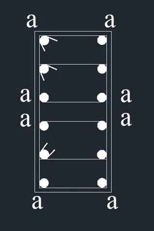
c) Column C2 of size 9"X24" having 20mm dia 8 bars as shown in figure "a" and rest 12mm dia 4 bars with 8mm dia stirrup.
- Now we draw a rectangle using reactangle command of size 9"X24" by dimensions method.
- By using offset command: give an offset of 0.5" to the rectangle in outward direction which will be cover for the column.
- Now by using the explode command: explode the inner rectangle.
- Now we draw the reinforcements:
- By using the circle command: selecting tan tan radius circle and give the radius of 0.35".
- Using mirror command create the reinforcement on the bottom left side of column by giving plane as the midpoint of the 2' line and click on NO for erase source object.
- Now by using divide command: divide the 2' line into 5 segments.
- To make the points visible type"DDTYPE" in the command box and apply a suitable point.
- Now create circle of radius 0.23" and place it centre rest of the points and mirror it as in previous step.
- Now copy the circle using the top of the circle as the base point and place it on the points created by object snap.
- Place all the 4 circles on the each divided point and then delete the points created.
- Create similar circles on the right side by using the mirror command.
- Now we draw the stirrups:
- Connect the reinforcement by using line command for the 2nd and 4th row on top and 3rd and 5th row on bottom.
- Connect them as tangents of two circles.
- Now fillet the corners of the column with radius as 0.4".
- Now using the donut command fill the circles.
- Specify the inner dia as 0 and outer dia as 0.70 and 0.4"" .
- Specify the centre of donut and fill the circles.
- Mark"a" with single text on side of 20mm diameter reinforcement for identification.
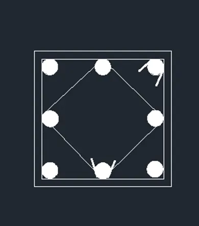
d) Drawing column C2a:
- We draw a rectangle of 9"X10" and give offset of 0.5" and then explode the offseted rectangle.
- Now we draw the reinforcement:
- By using the circle command: tan tan radius select the two corners and give radius as 0.3"(8mm)
- Mirror these to the corners of the rectangle.
- Draw lines joining the midpoint of each side then by by circle command give radius as 0.3".
- Mirror the circles on opposite side using mirror command.
- Fill the reinforcement by donut command give inner diameter as 0 and outer as 0.6".
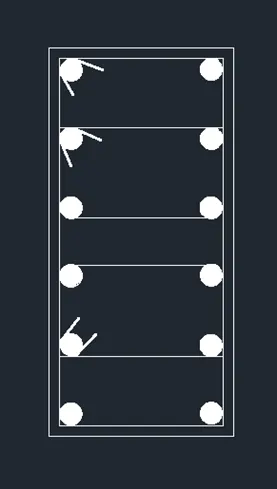
e) Drawing the column C3 of siize 9"X21" reinforcement of 16mm dia 12 nos and stirrups of 8mm diameter.
- We draw a rectangle of 9"X21" and give offset of 0.5" and then explode the offseted rectangle.
- Now we draw the reinforcement:
- By using the circle command: tan tan radius select the two corners and give radius as 0.3"(8mm)
- BY using mirror command: mirror the circles to four corners of the column.
- Divide the 21" line into 5 segments and 4 points are created.
- Copy the circle and place it in the midpoint of the points by"CO" command.
- Mirror the copied circles on the other side and delete the points created.
- Now we draw the stirrups:
- Connect the reinforcement by using line command for the 2nd and 4th row on top and 3rd and 5th row on bottom.
- Connect them as tangents of two circles.
- Now fillet the corners of the column with radius as 0.3".
- Now using the donut command fill the circles.
- Specify the inner dia as 0 and outer dia as 0.6.
- Specify the centre of donut and fill the circles.
- Place each of the drawn columns in the respective table making it a scale of 4".
- Using "SC" command select the object select the base point and scale factor as 4".
Result: The column schedule is drawn.
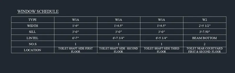
2. Window Schedule:
Aim: To draw the window schedule
Procedure:
- Take a table command
- Then specify the number of columns and number of rows of the table
- Then specify the point
- Table is displayed
- Now adjust the width of the column and the row height from the table properties
- Then select one cell of the table
- Type the text as given
- Change the alignment of the text from the table properties
- Format of the text can be changed by the table style command
- If you want to add a number of rows and number of columns can be added through table edit command.
Result: The template drawn is shown.
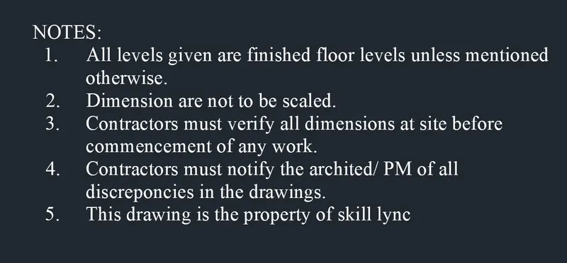
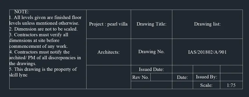
3.Creating template:
Aim: To create the template
Procedure:
- First we create the table by drawing a rectangle of length 40' and width 15'.
- Copy this rectangle and place it next to it with snap on and copy 2 of them.
- Using the copy command select the object and select the base point and select the point where we need to place the rectangle.
- Divide the 2nd column of table into two and 3rd column into 5.
- By using the offset command:with offset distance 3' select the object and create the rows.
- Divide the 3rd column into 4 each of 10' by offset command and trim off the extra lines.
- Now we insert the text:
- Select the multi line fron drop down list of text -create the text box and type tha given data.
- Text height is given as 8".
Result: The template drawn is shown.
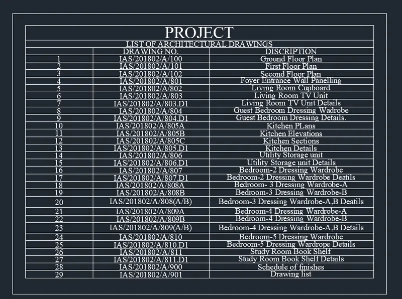
4. List of drawing schedule:
Aim: To create the list of drawings schedule.
Procedure:
- First, create the table with 31 rows and 3 columns
- Modify the table properties
- Select the cell type as the title for the first two rows
- Select the cell type as data for the remaining rows
- Adjust the width of the column from the table properties
- Select the text alignment as middle left in the table style
- Now type the text as given in the question.
Result: The template drawn is shown.
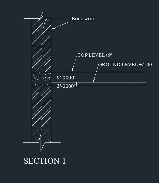
5.Beam detail:
Aim: To draw the beam detail
Procedure:
- Draw a cross-section of beam with height 4' and thickness 9"
- With line command draw a line of 4' in +y direction then 9" in + x direction and 4' downwards and close.
- From the top give an offset of 9" which marks the ground level using the offset command by giving distance as 9".
- Then give an offset of 3" from 9" line.Give an offset distance of 3" which indicate the bottom level of concrete.
- Hatch the portion of brick and concret and trim off the line of ground level fro the cross-section of the beam.
- Now we insert the text:
- Select the multi leader from the annotate tab and write the text with text height of 2".
- Type the text"TOP LEVEL +9" at the top of 9" line,type "GROUND LEVEL+/-00" At the 3" ground line.
- Type "BRICKWORK" indicating the part of brickwork using multileader.
- With the multiline text from the text dropdown type "SECTION 1" at bottom of the figure at 2" height.
Result: The beam detail is drawn.