Creation of Column Schedule and Drawing Template using AutoCad
AIM:
(a). Create a column schedule as shown in the figure.
Create a column schedule with the help of lines. Also, insert text with the help of Dtext command or Single Line text.
(b). Create a window schedule as shown in the attached figure(b):
(c). Create the drawing template as shown in the figure(c)
(d). Create the list of drawing schedule as shown in figure(d)
(e). Create the Beam detail as shown in the figure and provide text wherever given.
INTRODUCTION: -
- FIRSTLY, define the units required for drawing with precision using "UN" command.
- after defining the units with precision, assign the origin before proceeding further.
- Here I have defined the units in architectural form (Feet, inches) with precision of 0.000 having lightning option of generic form.
- I have approximated the data of column/footing configuration as given below:
| Elements of structure | in mm(proposed at site) | in inches (in the drawing) |
| clear cover | 25 | 1" |
| R/F of stirupps | 8 | 0.33" |
| R/F LONGITUDINAL bars | 12 | 0.5" |
| 16 | 0.67" | |
| 20 | 0.8" |
- Every ring of stirrup has only one hook whose configuration is shown in figure (a) with a dimension of >2" at 135degree angle.
- use "merge" option where ever require to combine rows or column in the table attached below.
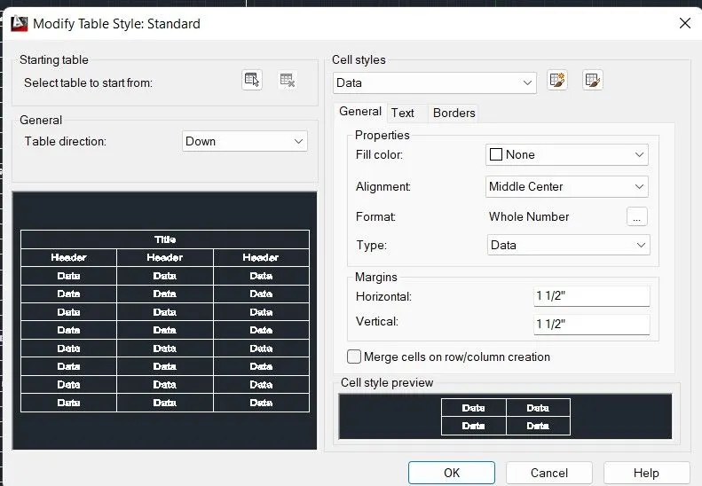
- Define the table properties from annotate command in the home tab & make the arrangement as per the need of the drawing.
- Always aware to provide a scale to a particular type of drawing otherwise it may cause irregularities in the preceding sketch while switching over to next drawing with exaggerated/minimal scale option.
PROCEDURE:
FIGURE (a)
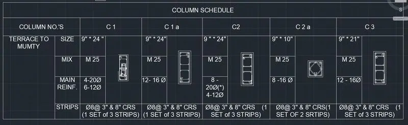
1. select "INSERT" command from the "HOME" tab and define the no. of rows & columns required.
- Define the Table properties like spacing between rows/column, text height & style, alignment of text etc. in GENERAL, TEXT & BORDER OPTION.
- Define the properties of first, second & third row at the commencement of work Otherwise leads to delaying in sketching.
- Use line command with track option to draw the column r/f in above figure.
- Hooks are of >= 2" with angle of 135degree.
- Placing of hooks in a structural element should be staggered due to random behaviour of stress generation due to seismic effect.
- Last row of the above table is defining the no. of stirrups at a particular section. For Example: (1 SET OF 3 STIRRUPS) means 3 kinds of stirrups (open or closed stirrups) are placed at a particular section with arrangement as shown above.
FIGURE(b):
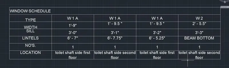
1. Select Table option from the HOME tab and modify the properties in the upcoming popup window after selecting MODIFY option.
- Define the properties of first three rows in a table as per the needs.
- Use 'merge' option to merge rows/column by clicking right side button of mouse over the selected rows/columns.
- For selecting multiple cells in a queue, firstly select single box and after this, click on the corner side of that box, long left-hand mouse press Drag the mouse in the direction of selection as per the requirement to make a modification.
- Define the Text height or other properties which have already mentioned in introductory part.
Here I have used the following properties:
first row: TITLE
Second row: Header
Third row: data
text height: 2"
alignment: middle-top in first column while middle-center in the remaining column.
- Don't forget to define the data type of a table otherwise a popup window will open after every entry of data with an alert.
FIGURE (c):

1. It's better to write the text using MULTIPLE TEXT option in the HOME Tab.
- Define the Scale & text height, style etc. required to make the above table.
- after texting the lefthand side portion, select table option & follow the same instruction required in the figure(b) to make a table.
- after completion of table along with Texting on the left side of attached pic. above, combine the two using MOVE/COPY COMMAND.
- After this, use "rec" command to enclose the above data with adequate margins around.
FIGURE(d):
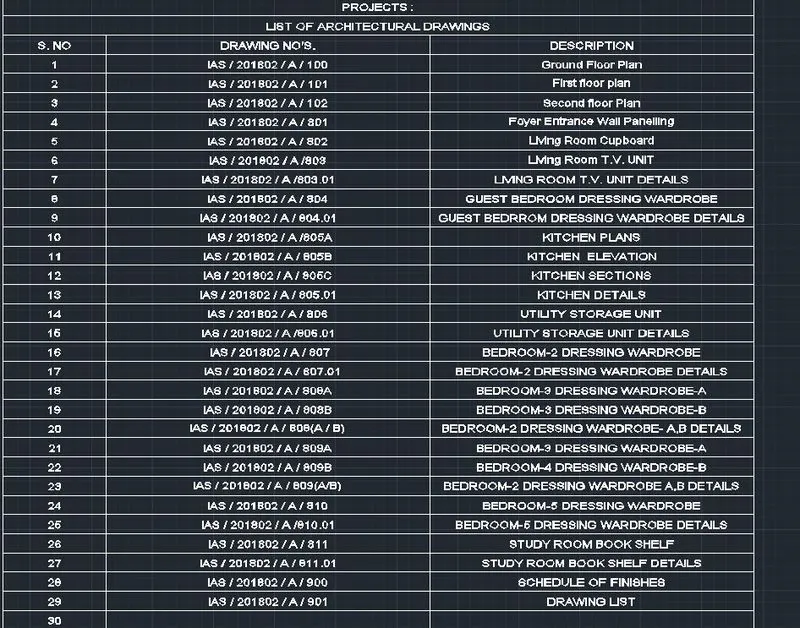
1. Select TABLE option from the HOME tab and define the properties using modify option available in the upcoming popup window.
2. here i have use following properties in the sections named as General, TEXT & Spacing.
alignment: middle-center
font size: 2"
font: arial
FIGURE(e):
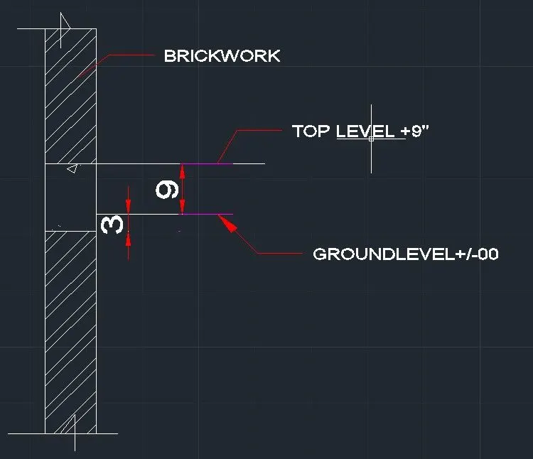
figure(e)
- Using line command to draw the section of beam 9" * 12"
- Wall are made on both sides of beam cross-section of arbitrary dimensions.
- After Drawing the sketch mentioned in the given challenge, define the properties of lines, arrows & symbols, text, primary units etc. in the annotate option before proceeding for labelling & texting.
- use Dim linear option to give the labelling & select text option in the annotate button.
5.After all, select hatch pattern to lodge the closed portion separately.
- we may adjust the hatching pattern by various options available in the hatch-edit command.
RESULT: -
i have sketched all the drawing in the AUTOCAD software as mentioned in the challenge & attached here in the form of screenshots at the final preparation of drawing.