Creation of Column Schedule and Drawing Template using AutoCad
Week 5-Assignment 5-Module 2
Aim: To sketch and edit the requested layout using the different drawing, modifying tools with application of advanced editing tools covered in week 5 sessions.
Introduction:
- The topics covered in week 5 (titled Start Advanced Sketching and Editing III and Drawing Aids) which are essentials in plotting the requested geometries are as follows;
- Grips, these are the small squares that appears when objects are selected with the cross hairs directly from the command prompt. Grips allow AutoCAD drawings to be edited in an entirely new way. Without entering any edit commands; you can stretch, move, copy, rotate, scale, and mirror entities.
- Match Properties, this allows you to quickly copy properties such as layer, color, and linetype from one AutoCAD entity and apply them to another.
- Hyperlink, this feature allows you to associate a drawing object with a hyperlink. Hyperlinks can point to local files, or files at an intranet or Internet location. Hyperlinks are stored as part of the XData of the associated object and can have descriptive text about the contents of the file.
- Quick Selection, is a filtering selection tool that allows you select the objects you want. There are 4 ways to open Quick Select in AutoCAD: Home tab> Utilities panel>Quick Select. With no command active, right-click in the drawing area and choose Quick Select.
- Selection Set, this allow you to group objects together and then modify them. For example, if you want to erase several lines, you could press E <ENTER>, pick on the line, press <ENTER> again and repeat until you're done.
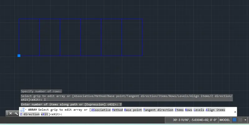
- Array Option, array is the command used to draw multiple copies of an object in a particular pattern or order. We can also manage the distance between the objects in the array. The shortcut key for Array is AR. To implement an array, we can type Array or AR on the command line and then press Enter.
- Utilities Option, is a temporary action. It doesn’t fix on sheet after applying for further reference. It is for the immediate requirement that occurs at the specific time. Refer to below listed for functions under the utilities options with its command shortcut;
- Measure – MEASUREGEOM
- Id point – ID
- Point style – PTYPE
- Quick calculator – QUICKCALC
- Quick select – QSELECT
- Select all – AI_SELALL
- List Command, you can use LIST to display and then copy the properties of selected objects to a text file. The text window displays the object type, object layer, and the X,Y,Zposition relative to the current user coordinate system (UCS) and whether the object is in model space or paper space. It also shows further information about the selection object such as line type, thickness etc.
- ID Command, allows you to locate a point on a drawing and have the position of the point displayed in coordinates. AutoCAD remembers the coordinate location of the point.
- Time Command, displays information such as last update, creation date, edit times and other statistics pertaining to your current drawing. It is revised whenever you save the drawing files.
- Status Command, reports the number of objects in the current drawing. This includes graphical objects such as arcs and polylines, and nongraphical objects such as layers and linetypes, and block definitions.
- Zoom Command, Increases or decreases the magnification of the view in the current viewport. You can change the magnification of a view by zooming in and out, which is similar to zooming in and out with a camera. Using ZOOM does not change the absolute size of objects in the drawing. It changes only the magnification of the view.
- Saving the View, this will help you save time if you save the views, then you can quickly load it later any time you need it.
- Annotation, this include dimensions, notes, and other types of explanatory symbols or objects commonly used to add information to your drawing. Annotation objects provide information about a feature, such as the length of a wall, the diameter of a fastener, or a detail callout. Typically, annotation objects are scaled differently than the views of the drawing, and depend on the scale of how they should appear when plotted.
- Annotation Scale, used to determine text height or the overall scale of an annotation object.
- Text, there are two kinds of text that can be used in AutoCAD, Multiline and Single Line. You have more control over the appearance of Multiline Text and if you move the text, multiple lines stay grouped together. Single Line text is useful for writing out a collection of notes; each return creates a separate entity. This is useful for writing out multiple single line notes, such as room names, that can be moved around the screen independently from each other. Dynamic Text or with command DTEXT is also s single-line text object, showing the text dynamically on the screen as it is entered.
Procedure:
A. Starting AutoCAD;
- Search for the AutoCAD icon from your desktop and double click it to make it run or you may search it from windows search tool and open from there if no shortcut in the desktop.
- You may simply click the “Get Started-Start Drawing” icon once the AutoCAD is opened or you may click the Application Menu tab with the “A” AutoCAD logo on the top -left most side of the screen and select new. From the new you may find a variety of templates that suits your requirements.
- For this exercise, we will just simply proceed on Get Started-Start Drawing” icon and set up the measurement units inline with the drawing requirements.
B. Setting the Drawing Parameters;
- Set up the measurement units according to sketched information provided.
- To set up that, a much faster way is to type “units” in the command line and hit enter or space bar. The Drawing Units Dialog box will then pop up and measurement parameters will then set up in line with the requirements. Similar thing, you need to set up the dimension through the DDIM command.
- As for the gridlines, you may right click gridline icon in the status bar and go for the drafting settings. Under the Snap and Grid of the Drafting Settings Dialog box, you may set up the needed spacing of grids along its X and Y axis. “DS” command will also work to pop up the Drafting Settings Dialog box.
C. Starting the exercise;
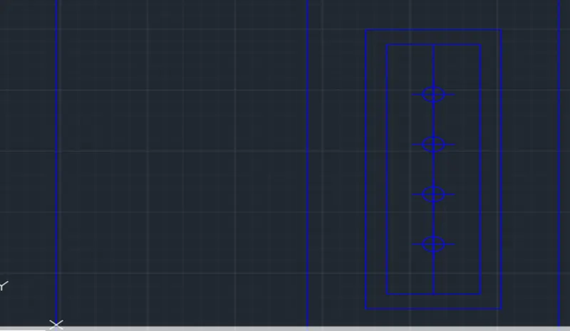
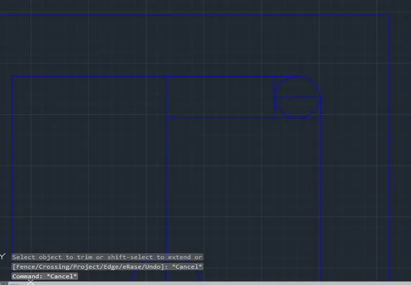
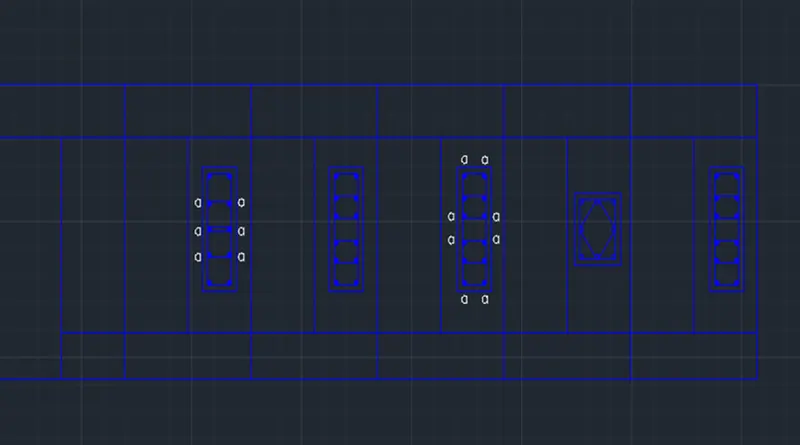
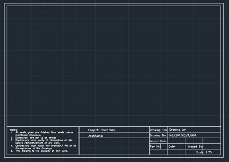
- Combination and manipulation of all the different coordinate entry methods, drawing and modifying tools learned from weeks 1 to 5 were being used here in the completion of all the exercises given and result as pasted below.
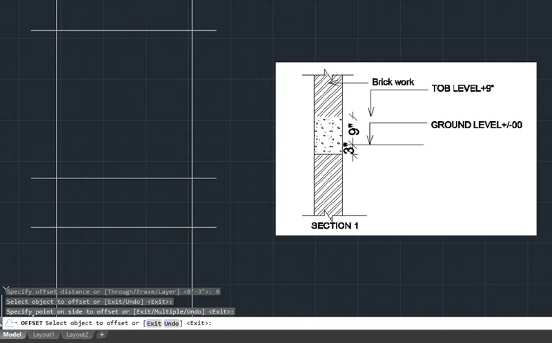
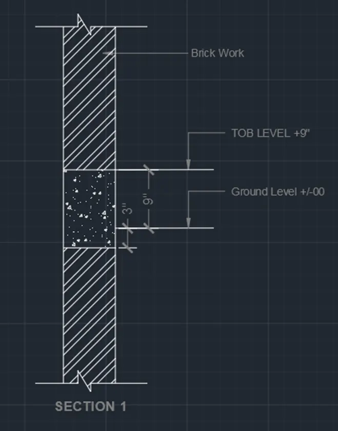
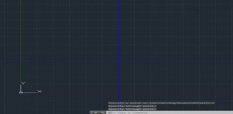
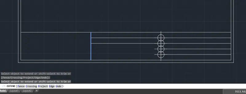
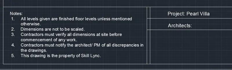
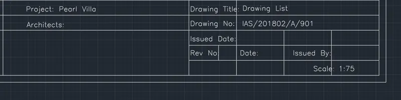
- I have attached some screenshots while plotting the needed five exercises to show the procedure on how it was done to come out with the requested layouts.
- Please take noted that TABLES was not covered in the previous sessions and yet very much needed for the exercises given.
D. Challenge;
- In general, below commands/functions were being used while working on the exercises.
- Units
- LIMITS
- LIMMAX
- DDIM
- XLINE
- LINE
- PLINE
- OFFSET
- DIVIDE
- PTYPE
- ARRAY (AR)
- MIRROR (MI)
- CIRCLE
- TABLE
- FILLET
- TEXT
- MTEXT
- DTEXT
- LEADER
- Manipulation with Ortho mode and Object Snaps
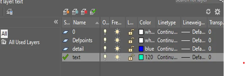
- LAYERS
- UTILITIES
- MATCHPROP
- ANNOTATION
Challenge 1.
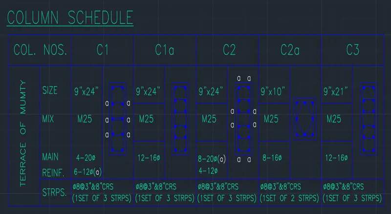
Challenge 2.
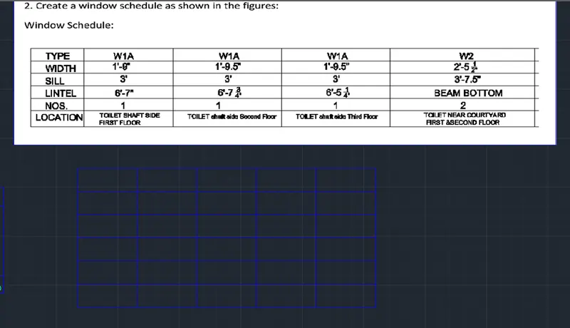
WINDOW SCHEDULE
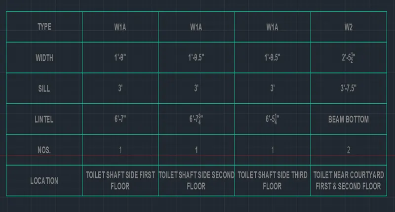
Challenge 3.
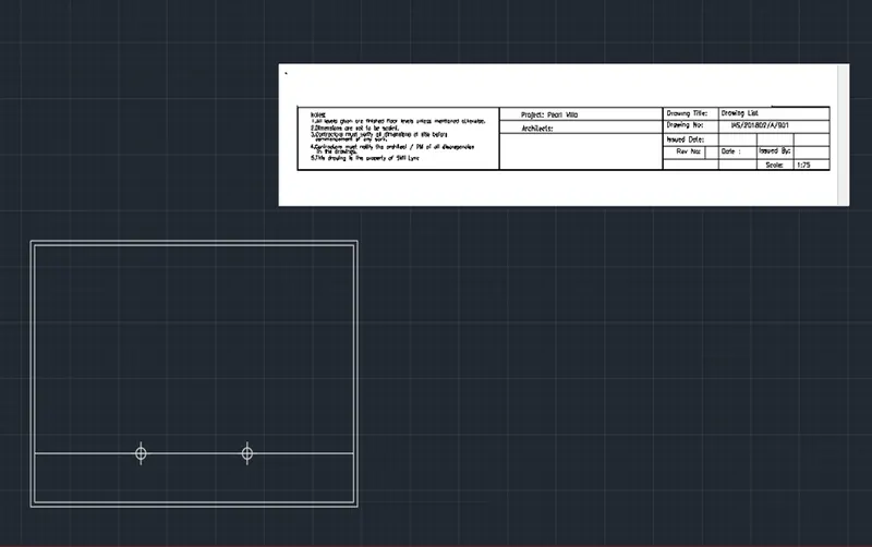

Challenge 4.
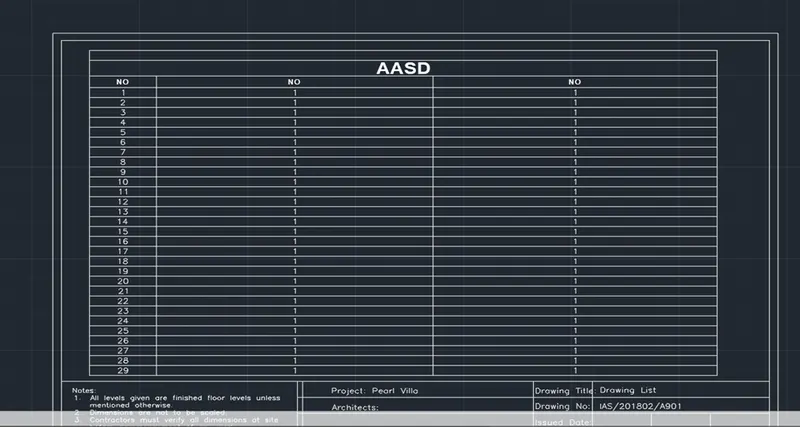
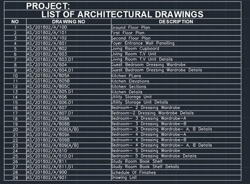
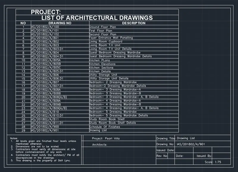
Challenge 5.