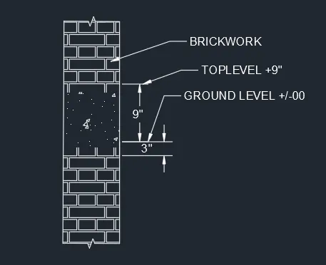
Creation of Column Schedule and Drawing Template using AutoCad
CHALLENGE 5
- CREATING COLUMNS AND COLUMNS TABLE.
AIM – To create a column schedule with the help of the lines using AutoCAD software.
Procedure:
- Open the Autocad software and set the imperial template.
- Set the units to architectural and give the desired length and width of drawing.
- Creating C1 column
- Give the rectangle command REC and give the length as 9” and width as 24”. Rectangle will be created.
- Give the offset command of 0.5” in the inner side to make the inner rectangle.
- Now using the line command make the lines in the inner rectangle at desired distance as shown in figure.
- Now use the DONUT Command to make the bars dots as shown as a front view.
- At free space Use donut command and give the inner radius as 0 and outer radius as 2”.
- Now use COPY command and Copy the bar dot to the inner rectangle’s upper horizontal line and keep it at centre below the horizontal line.
- This is done so that dot should touch the both corner line of rectangle when it is moved and do not get misplace.
- Now again use the copy command and keep dots at required points seen in drawings.
- zoom the geometry and use the fillet command FILLET.
- By clicking at the centre of small upper left corner bar dot, give the radius till upper line of rectangle.
- Click on Polyline and then click on both the corner lines of rectangle. whole rectangle corners will be filleted.
- Now again use a donut command and make a filled donut of inner radius 0 and outer radius 2”
- Now use a explode command and click on 2” donut
- White colour will get removed.
- Now from both the right and left side of circle give a vertical tangent.
- Now use TRIM command to trim the lower semicircle.
- U shape small size bar is created for tying corners at stirrups.
- Use the rotate command and give the angle as 45 degree.
- Copy and keep it at required points as shown in figure.
- Now give the Text command and click on multiline text.
- Give the font as Romans.shx and type "a" and put it at desired points using COPY command.
- Geometry of column has been created.
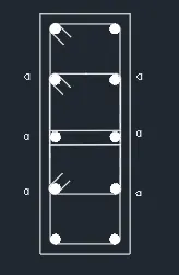
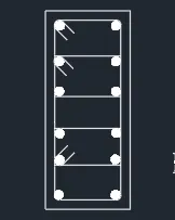
- Creating C1a column
- Give the rectangle command REC and give the length as 9” and width as 24”. Rectangle will be created.
- Give the offset command of 0.5” in the inner side to make the inner rectangle.
- Now using the line command LINE make the lines in the inner rectangle at desired distance by dividing it in 5 segments as shown in figure.
- Now use the DONUT Command to make the bars dots as shown as a front view.
- At free space Use donut command and give the inner radius as 0 and outer radius as 2”.
- Now use COPY command and Copy the bar dot to the inner rectangle’s upper horizontal line and keep it at centre below the horizontal line.
- This is done so that dot should touch the both corner line of rectangle when it is moved and do not get misplace.
- Now again use the copy command and keep dots at required points seen in drawings.
- Zoom the geometry and use the fillet command FILLET
- By clicking at the centre of small upper left corner bar dot, give the radius till upper line of inner rectangle
- Click on polyline seen in command box while using fillet command and then click on both the corners lines of rectangle. Rectangle corners will get curved
- Now again use a donut command and make a filled donut of inner radius 0 and outer radius 2”
- Now use a explode command and click on 2” donut
- White colour will get removed.
- Now from both the right and left side of circle give a vertical tangent.
- Now use TRIM command to trim the lower semicircle.
- U shape small size bar is created for tying corners at stirrups.
- Use the rotate command and give the angle as 45 degree.
- Copy and keep it at required points as shown in figure.
- Column has been created.
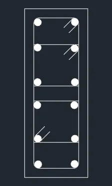
- Creating C2 column
- Give the rectangle command REC and give the length as 9” and width as 24”. Rectangle will be created.
- Give the offset command of 0.5” in the inner side to make the inner rectangle.
- Now using the line command LINE make the lines in the inner rectangle at desired distance by dividing it in 5 segments as shown in figure.
- Now use the DONUT Command to make the bars dots as shown as a front view.
- At free space Use donut command and give the inner radius as 0 and outer radius as 2”.
- Now use COPY command and Copy the bar dot to the inner rectangle’s upper horizontal line and keep it at centre below the horizontal line.
- This is done so that dot should touch the both corner line of rectangle when it is moved and do not get misplace.
- Now again use the copy command and keep dots at required points seen in drawings.
- Zoom the geometry and use the fillet command FILLET
- By clicking at the centre of small upper left corner bar dot, give the radius till upper line of inner rectangle
- Click on polyline seen in command box while using fillet command and then click on both the corners lines of rectangle. Rectangle corners will get curved
- Now again use a donut command and make a filled donut of inner radius 0 and outer radius 2”
- Now use a explode command and click on 2” donut
- White colour will get removed.
- Now from both the right and left side of circle give a vertical tangent.
- Now use TRIM command to trim the lower semicircle.
- U shape small size bar is created for tying corners at stirrups.
- Use the rotate command and give the angle as 45 degree.
- Copy and keep it at required points as shown in figure.
- Now give the Text command and click on multiline text.
- Give the font as Romans.shx for creating “a”
- Column has been created.
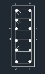
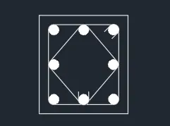
Creating C2a column
- Give the rectangle command REC and give the length as 9” and width as 10”. Rectangle will be created.
- Give the offset command of 0.5” in the inner side to make the inner rectangle.
- Now use the DONUT Command to make the bars dots as shown as a front view.
- At free space Use donut command and give the inner radius as 0 and outer radius as 2”.
- Now use COPY command and Copy the bar dot to the inner rectangle’s upper horizontal line and keep it at centre below the horizontal line.
- Use the move command MOVE and put the bar view dot at the corner.
- Now use the mirror command and put the bar dot at all the corners.
- Now use the offset command from the centre of bar dot.
- Give the offset distance till the circumference
- Line is created as tangent from bar dot till the lower bar dot.
- Repeat the same for other getting other lines.
- Now again use a donut command and make a filled donut of inner radius 0 and outer radius 2”
- Now use a explode command and click on 2” donut
- White colour will get removed.
- Now from both the right and left side of circle give a vertical tangent.
- Now use TRIM command to trim the lower semicircle.
- U shape small size bar is created for tying corners at stirrups.
- Use the rotate command and give the angle as 45 degree.
- Copy the U shape bar and keep it at required points.
- Geometry has been created.
- Creating C3 column
- Give the rectangle command REC and give the length as 9” and width as 21”. Rectangle will be created.
- Give the offset command of 0.5” in the inner side to make the inner rectangle.
- Now using the line command LINE make the lines in the inner rectangle at desired distance by dividing it in 5 segments as shown in figure.
- Now use the DONUT Command to make the bars dots as shown as a front view.
- At free space Use donut command and give the inner radius as 0 and outer radius as 2”.
- Now use COPY command and Copy the bar dot to the inner rectangle’s upper horizontal line and keep it at centre below the horizontal line.
- This is done so that dot should touch the both corner line of rectangle when it is moved and do not get misplace.
- Now again use the copy command and keep dots at required points seen in drawings.
- Zoom the geometry and use the fillet command FILLET
- By clicking at the centre of small upper left corner bar dot, give the radius till upper line of inner rectangle
- Click on polyline seen in command box while using fillet command and then click on both the corners lines of rectangle. Rectangle corners will get curved
- Now again use a donut command and make a filled donut of inner radius 0 and outer radius 2”
- Now use a explode command and click on 2” donut
- White colour will get removed.
- Now from both the right and left side of circle give a vertical tangent.
- Now use TRIM command to trim the lower semicircle.
- U shape small size bar is created for tying corners at stirrups.
- Use the rotate command and give the angle as 45 degree.
- Copy and keep it at required points as seen in geometry
- Column has been created.
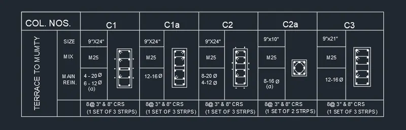
- Creating the column table.
- Give a rectangle command REC and make a rectangle of length 3’8.25” and width 1’0.75”.
- Type the offset command and from the upper horizontal line of rectangle give the offset of 2.25” downward in +y direction
- Now from the left vertical line rectangle give the offset of 7.25” in +x direction.
- Give the same offset and make 6 columns parts.
- Now from lower rectangle horizontal line give the offset of 2” in +y direction.
- Trim off the required lines.
- Now from left vertical line of rectangle from middle give the offset of 4.25” in +x direction.
- Now again give the offset from last point of 6.25” in +x direction.
- Now again give the offsets of 7.5” four times in same direction for getting required columns in tables
- Use the single line text.
- Type the required text shown in table.
- Table has been created.
Result: Coulmns and coulmn schedule has been created as per given in geometry.
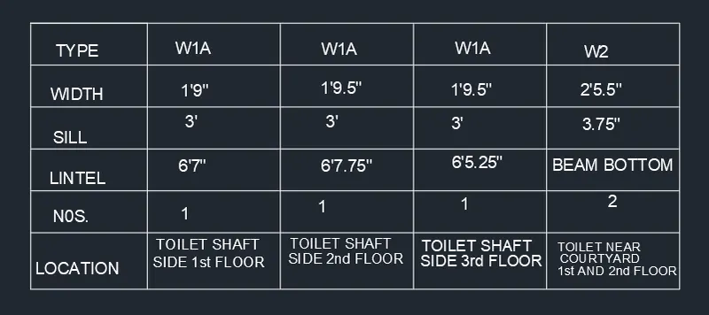
- Window schedule
Aim- To draw the window schedule as shown in figure.
- Open the Autocad software and set the imperial template.
- Set the units to architectural and give the desired length and width of drawing.
- Type the REC command and make rectangle of length=2’2.75” and width = 11”
- From the upper horizontal line of rectangle give the offset of 1.75”in –y direction
- Give the same offsets for making other rows in tables.
- From the left vertical line of rectangle give the offset of 4.75” in +x direction.
- Give the same offset for making the other columns in the table.
- Use the single line text for typing and keeping the height as 0.5”
- Window schedule created.
Result: Window schedule has been drawn as per the given figure.
- Drawing template
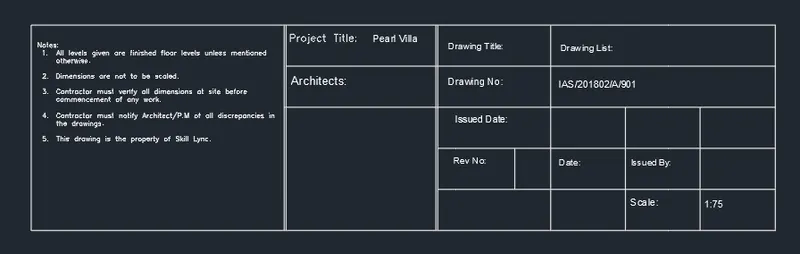
Aim- To draw the Drawing Template as shown in figure.
- Open the Autocad software and set the imperial template.
- Set the units to architectural and give the desired length and width of drawing.
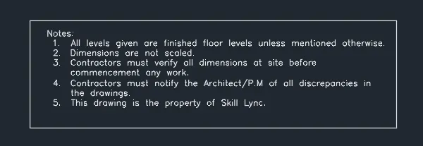
- Type the REC command and make rectangle of length=2’6.75” and width = 9”
- Use the multiline text and type the text by keeping the font as Romans.shx and text height as 0.5”
- Notes template is created.
- Creating table
- From the left vertical line of rectangle give the offset of 2’2.75” in =x direction.
- Now again give the offset of 0.5” in +x direction.
- Now again give the offset of 1’3.75” in +x direction.
- Now again give the offset of 0.5” in +x direction.
- Now again give the offset of 1’ in +x direction.
- From the upper horizontal line of rectangle give the offset 4.25” in –y direction.
- Repeat the same offset for getting other rows.
- Trim off the required lines.
- Now from the right vertical line of 3rd column give the offset of 8” in +x direction.
- Give same offset again in +x direction.
- Trim off the required line.
- Template and table has been created.
Result: Drawing template has been created as per given in the figure.
4.Drawing schedule
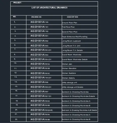
Aim- To draw the Drawing schedule as shown in figure.
- Open the Autocad software and set the imperial template.
- Set the units to architectural and give the desired length and width of drawing.
- Type the REC command and make rectangle of length=7’0.5”and width = 9’8”
- From the upper horizontal line of rectangle give the offset 4.5” in –y direction.
- Repeat the multiple offsets of same length for getting the required nos. of rows
- Now using erase command erase the 2nd offset line for getting thicker row.
- Now from left vertical line of rectangle give the offset 1’3.25” in +x direction.
- Now again give the offset of 2’10.5” in same direction.
- Now use the single line text using text command and give the height of text as 0.5”
- Drawing schedule has been created.
Result: Drawing schedule has been drawn as per given in the figure.
- Beam Details
Aim- To draw the beam and provide details as shown in figure.
- Open the Autocad software and set the imperial template.
- Set the units to architectural and give the desired length and width of drawing.
- Type the REC command and make rectangle of length=1’and width = 4’
- Now from the upper horizontal line give the offset of 10” in –y direction.
- Now again give the offset of 1’ –y direction.
- Now use trim command TRIM and trim the upper and lower horizontal line of rectangle.
- Now use BREAK LINE Command and make the line by selecting upper two corners of rectangle of trimmed line.
- Repeat same for lower side.
- Now use HATCH Command and hatch the middle portion and remaining portion by selecting specific hatch pattern.
- Now use the leader for marking
- Use DIMLINEAR for dimensioning.
- Beam detailing has been done.
Result: Beam is created and detailing is done as per given in the figure.