Creation of Column Schedule and Drawing Template using AutoCad
COLUMN SCHEDULE
Aim:
To draw a column schedule in AutoCAD with all the reinforcement details
Procedure:
Draw Workspace
- Open a workspace
- Set UNIT as Architectural from the dropdown with the precision of 1” and input inches
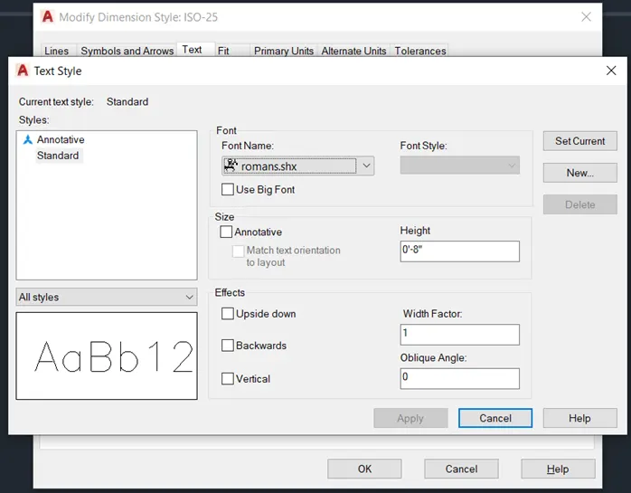
- Type DIMSTY and set the dimensions as set in the unit window in 2nd step
- Set font name as romans.shx with the height of 8” and justified to left
Draw a table for the format
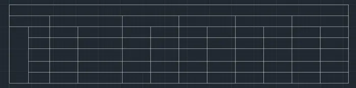
- Type TABLE and enter 5 rows and 12 columns to create a table
- Specify the insertion point and suitably edit the table to making format as required in question by merging cells
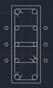
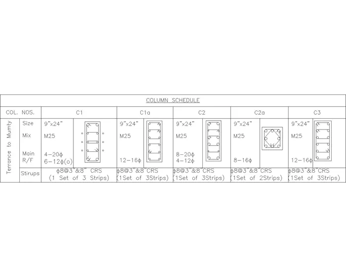
Draw Column C1
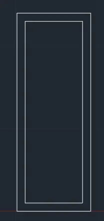
- Draw a RECTANG of the size of 9”x24”
- Use EXPLODE command to separate each part of the rectangle
- Specify clear cover of 1” from all sides by using OFFSET of 1” from all sides
- Use FILLET command to remove the excess drawing
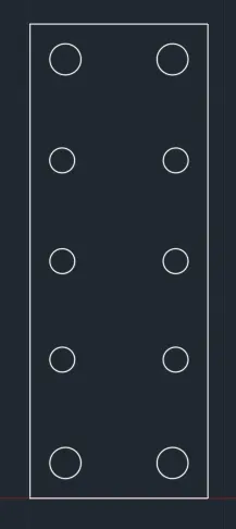
- Draw two different CIRCLE to represent 20mm dia and 16mm bars
- Place 20mm circles at four corners of clear cover
- Place 16mm circles nos 6 in-between places of corners in the vertical direction only
- To place 16mm bars in between 20mm bars, draw a LINE between two 20mm and DIVIDE it in 4 segments for even placement
Draw 3 strips for C1
- Draw 1st strip from first top R/F to third R/F using LINE and ARC command
- Draw 2nd strip from second top R/F to fourth R/F using LINE and ARC command
- Draw 3rd strip from third top R/F to sixth R/F using LINE and ARC command
- Give the anchorage bending of 135 degrees and 4 times of diameter to each strip
- Mark all the 16mm diameters with the circles posted outside the column for identification
Drawing of C1a
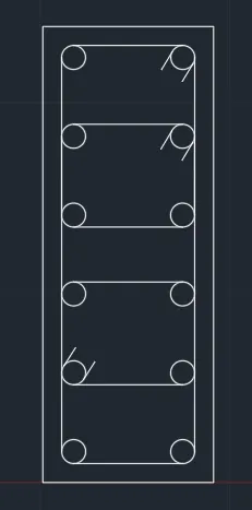
- Draw a RECTANG of the size of 9”x24”
- Use EXPLODE command to separate each part of the rectangle
- Specify clear cover of 1” from all sides by using OFFSET of 1” from all sides
- Use FILLET command to remove the excess drawing
- Draw CIRCLE to represent 16mm bars
- Place 16mm circles at all locations as shown
- To place in between 16mm bars in between corner 16mm bars, draw a LINE between two corners 16mm and DIVIDE it in 5 segments for even placement
Drawing of stirrups for C1a
- Draw full strip covering all the 12 bars using LINE and ARC command
- Draw two small strips as shown using LINE and ARC command
Drawing of C2
- Draw a RECTANG of the size of 9”x24”
- Use EXPLODE command to separate each part of the rectangle
- Specify clear cover of 1” from all sides by using OFFSET of 1” from all sides
- Use FILLET command to remove the excess drawing
- Draw two different CIRCLE to represent 20mm and 12mm bars
- Place 20mm circles at all locations as shown
- To place the remaining 20 mm bars and 12 mm bars DIVIDE the line between opposite corners 20mm into 5 segments
Drawing of stirrups for C2
- Draw full strip covering all the bars using LINE and ARC command
- Draw two small strips as shown using LINE and ARC command
- Draw an extension of the strip at an angle of 135 degree
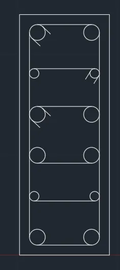
Drawing of C2a
- Draw a RECTANG of the size of 9”x10”
- Use EXPLODE command to separate each part of the rectangle
- Specify clear cover of 1” from all sides by using OFFSET of 1” from all sides
- Use FILLET command to remove the excess drawing
- Draw CIRCLE to represent 16mm bars
- Place 16mm circles at all corner locations as shown
- To place the remaining 16 mm bars DIVIDE the line between opposite corners 20mm in 2 segments
Drawing of stirrups for C2
- Draw full strip covering all the bars using LINE and ARC command
- Similarly, draw the stirrups for the middle R/F
- Draw an extension of the strip at an angle of 135 degree
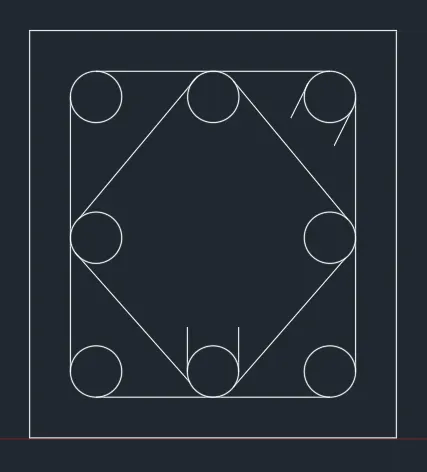
Drawing of C3
- Draw a RECTANG of the size of 9”x21”
- Use EXPLODE command to separate each part of the rectangle
- Specify clear cover of 1” from all sides by using OFFSET of 1” from all sides
- Use FILLET command to remove the excess drawing
- Draw CIRCLE to represent 16mm bars
- Place 16mm circles at all corner locations as shown
- To place the remaining 16 mm bars, DIVIDE the line between opposite corners 20mm in 5 segments
Drawing of stirrups for C3
- Draw full strip covering all the bars using LINE and ARC command
- Similarly, draw the 2 stirrups for the middle 2 R/F rows as shown separately
- Draw an extension of the strip at an angle of 135 degree
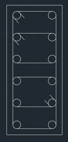
Inserting texts in table
- Put MTEXT command and type various texts in designated table cells
- Use text height as 8”
- “o” is shown in C1 for 12 mm bars
- For C2 difference of 20 mm and 12 mm is visible clearly
Results:
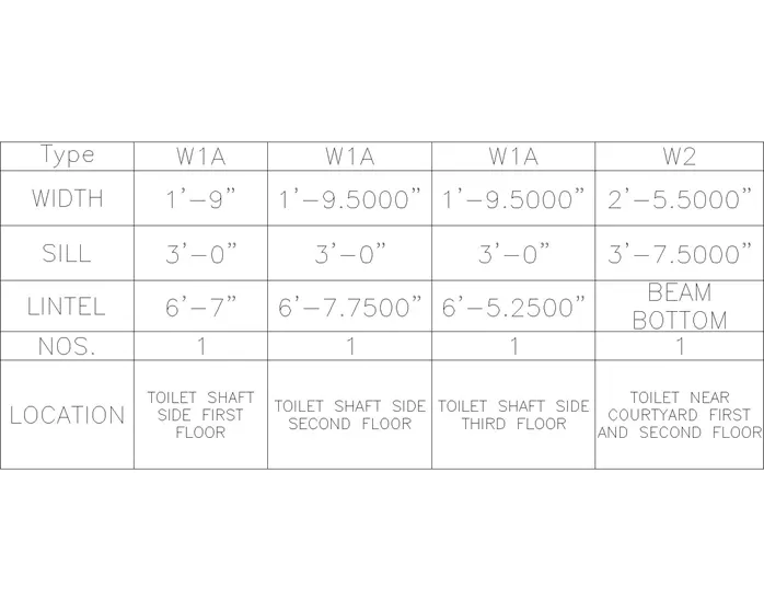
WINDOW SCHEDULE
Aim:
To draw a window schedule in AutoCAD
Procedure:
Draw Workspace
- Open a workspace
- Set UNIT as Architectural from the dropdown with the precision of 1” and input inches
- Type DIMSTY and set the dimensions as set in the unit window in 2nd step
- Set font name as romans.shx with the height of 8” and justified to left
Drawing of Table
- Use TABLE command to draw a table of 6 rows and 5 columns
Input of texts
- Use TABLEDIT command to input all the entries in the table
- Location font has been decreased to 5” for better visibility
Results:
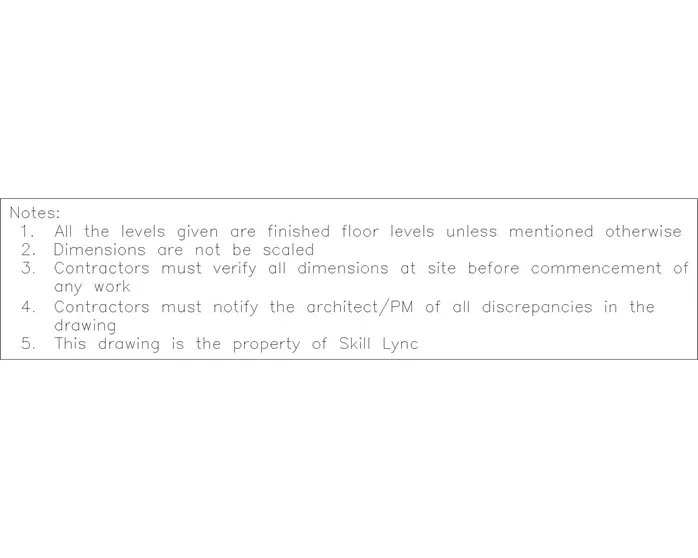
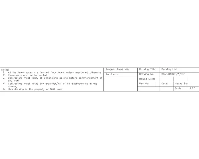
NOTE TEMPLATE
Aim:
To insert a note of a drawing in AutoCAD
Procedure:
Draw Workspace
- Open a workspace
- Set UNIT as Architectural from the dropdown with the precision of 1” and input inches
- Type DIMSTY and set the dimensions as set in the unit window in 2nd step
- Set font name as romans.shx with a height of 8” and justified to left
Insert text
- Type MTEXT command and specify the 1st point for start of text box
- Type the texts as given in the question
- Draw a RECTANG around the texts
- Similarly use RECTANG and MTEXT command to type other boxes
- Use LINE command to draw line in-between the texts
Results:
DRAWING SCHEDULE
Aim:
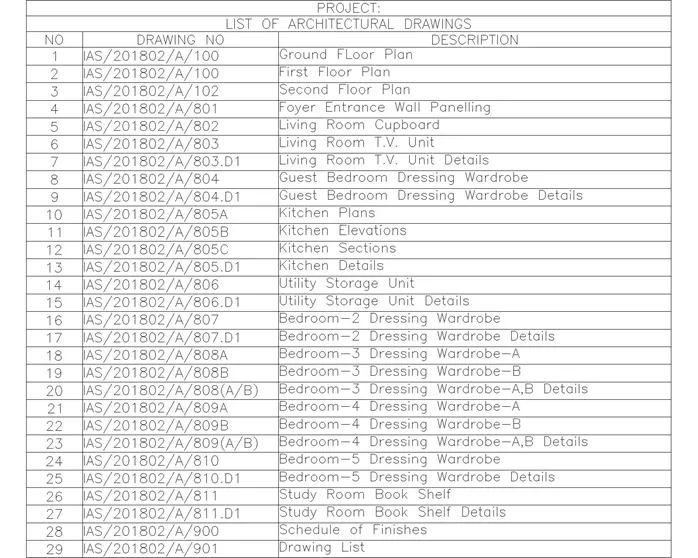
To insert drawing schedule in a drawing in AutoCAD
Procedure:
Draw Workspace
- Open a workspace
- Set UNIT as Architectural from the dropdown with the precision of 1” and input inches
- Type DIMSTY and set the dimensions as set in the unit window in 2nd step
- Set font name as romans.shx with a height of 8” and justified to left
Insert a table
- Use TABLE command to insert the table of 3 columns and 32 rows
- Insert point to fix the location of the table
- Use MTEXT command to type desired texts in each cell
- Merge top 2 rows for the entire column for heading
Results:
BEAM DETAILS
Aim:
To draw beam details in AutoCAD
Procedure:
Draw Workspace
- Open a workspace
- Set UNIT as Architectural from the dropdown with the precision of 1” and input inches
- Type DIMSTY and set the dimensions as set in the unit window in 2nd step
- Set font name as romans.shx with the height of 8” and justified to left
Beam drawing
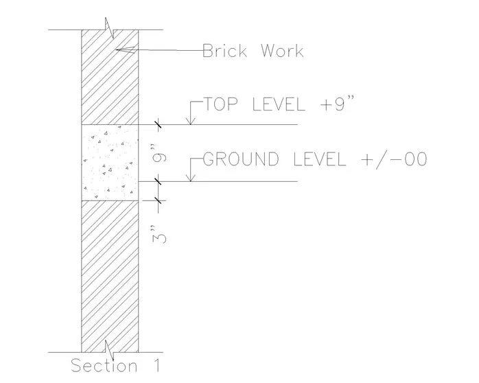
- Draw a LINE vertically
- OFFSET this line by 9” for beam thickness
- Draw bottom cut off section using LINE command
- Assume bottom brickwork to be 2’ and mark it using LINE command from the bottom
- Mark 1’ thick concrete portion of the beam
- Further mark 1’3” upper brickwork with a cutoff mark using OFFSET
- Mark ground level 3” above concrete bottom using OFFSET
- Mark top-level using OFFSET
- Use HATCH command to fill patterns in space as per the given drawing
- Use DIMLIN to measure dimensions
- Use MLEADER command to type texts
- MTEXT for type the name of section at the bottom
Results:
Conclusion:
In this assignment, there was extensive use of various AutoCAD commands like TABLE, TABLEEDIT, MTEXT, TXT2MTXT, LINE, COPY, HATCH, MOVE, CIRCLE, FILLET, OFFSET, DIM, MLEADER, and many more. Various drawings ranging from column schedule, beam section, a notes section, etc. was drawn in AutoCAD.
This calibrated use of each command gives a better understanding of AutoCAD and helps to make a broad and quick understanding of commands which can be used quickly and judiciously to save time during drawing.