Creation of Column Schedule and Drawing Template using AutoCad
- COLUMN SCHEDULE:
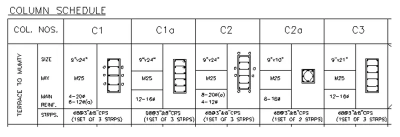
Aim: To prepare the column schedule
Procedure:
Step 1: Basic settings
- Open AutoCAD
- Open new drawing
- Set units (measurements as engineering, precision to 0’-0.0” , angle as decimal degree)
- Enable Ortho mode on
- Enter command dimstyle and click on modify
- Set unit to engineering and precision to 0’-0.0”
Step 2: Creating table:
- Create rectangle of 36'x10'
- By using offset tool, Command "O" - select the left side line and give offset distance as 6' first and for the second as 3'. Divide the 36' into 6' columns and again divide each 6' to 3'
- Create row at top and bottom of 2' and 3' respectively by offset command.
- Command "O" - select the top line and give distance as 2' again command "O" -select the bottom line and give offset distance as 2'.
- Trim off the unnecessary lines. Using trim tool
Step 3: Text
- Enter the text in the table by using single line text from the text drop down menu
- Specify the point of text specify text height as 8"
- Text angle as 0 degree,
- In case of the text “TERRACE TO MUMTY" give text angle as 90 degree
- Click on the top of the table and Give the heading as column schedule
- Now click at the selected points and enter text as given
- After entering the text, right click and select properties then list of properties will be displayed -ensure that the text height is 8" and make justify as left
- To change the style of text Command "ST, A dialogue box appears and select the font name
- Then insert all the text or copy the text created and edit it to the required text in respective rows and columns
Step 4: Drawing the column section:
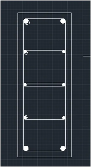
- Draw a rectangle using rectangle tool and give dimensions as 9” and 24”
- Select offset tool and give a offset length of 1” and produce inside offset of rectangle using cursor
- Select circle tool
- Start at a point and give a dia of 0.8” (20mm)
- Select move tool and move the circle to the top left corner of the inside rectangle
- Select copy tool and select the circle and move it to the all the corners
- Select division tool and divide the inside line into 4 parts
- Then type “DDPTYPE” in command box and give visible style for points
- Select circle tool
- Start at a point and give a dia of 0.5” (12mm)
- Select copy tool and select the circle and move it to the all the dot positions as given
- Select hatch tool then select solid and give solid to all the circles
- Select line tool and and connect the circles as shown in the fig to form stirrups
- Select arc and give at the hook position as given
- Now select all the drawing and give “join” command
- Follow the same procedure for all the other columns with their respective size and diameter of reinforcement
- Now select the columns and use move tool to place the columns in the table
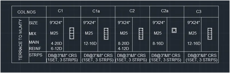
Result:
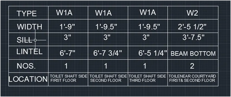
- WINDOW SCHEDULE:
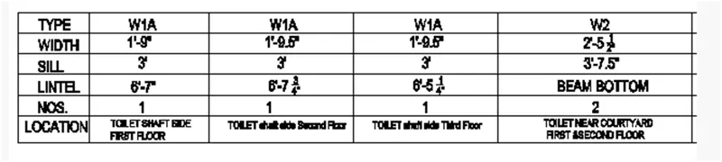
Aim: To prepare the window schedule
Procedure:
Step 1: Basic settings
- Open AutoCAD
- Open new drawing
- Set units (measurements as engineering, precision to 0’-0.0” , angle as decimal degree)
- Enable Ortho mode on
- Enter command dimstyle and click on modify
- Set unit to engineering and precision to 0’-0.0”
Step 2: Creating table:
- Select construction lines by using “XL” in command box
- Draw a vertical as well as horizontal line
- Use trim command and delete the bottom and left excess lines
- Select copy tool and select vertical line (at joint)
- Select array from command box
- give number as 6 and length as 5’
- move the cursor right side
- press enter
- Select copy tool and select horizontal line (at joint)
- Select array from command box
- give number as 7 and length as 2’
- move the cursor upwards
- press enter
- now select trim tool and delete the excess lines
Step 3: Text
- Enter the text in the table by using single line text from the text drop down menu
- Specify the point of text specify text height as 8"
- Text angle as 0 degree,
- Now click at the selected points and enter text as given
- After entering the text, right click and select properties then list of properties will be displayed -ensure that the text height is 8" and make justify as left
- To change the style of text Command "ST, A dialogue box appears and select the font name
- Then insert all the text or copy the text created and edit it to the required text in respective rows and columns
RESULT:
- CREATING TEMPLATE:

Aim: To create the template
Procedure:
Step 1: Basic settings
- Open AutoCAD
- Open new drawing
- Set units (measurements as engineering, precision to 0’-0.0” , angle as decimal degree)
- Enable Ortho mode on
- Enter command dimstyle and click on modify
- Set unit to engineering and precision to 0’-0.0”
Step 2: Creating table:
- Select line tool and start drawing a line
- From the start paint next point is @40’,0
- Next point @0,-15’
- Next point @-40,0
- Enter “c” to close the circuit
- Now select copy tool and select all lines press enter
- Select the base point and copy it side by side to form a total of 3 boxes
- Now select offset tool and give a distance of 3’
- Now select the top line of the 2nd box and move the cursor down wards and right click and select new line and move the cursor down wards and right click to form 2 lines as given
- Follow the same procedure for the 3rd box to form 5 rows as given
- Now select offset tool and give a length as 10’
- Select vertical line of the 3rd box and give offsets to form columns
- Now select trim tool to delete the unwanted lines as given
Step 3: Text
- Enter the text in the table by using single line text from the text drop down menu
- Specify the point of text specify text height as 8"
- Text angle as 0 degree,
- Now click at the selected points and enter text as given
- After entering the text, right click and select properties then list of properties will be displayed -ensure that the text height is 8" and make justify as left
- To change the style of text Command "ST, A dialogue box appears and select the font name
- Then insert all the text or copy the text created and edit it to the required text in respective rows and columns
RESULT:

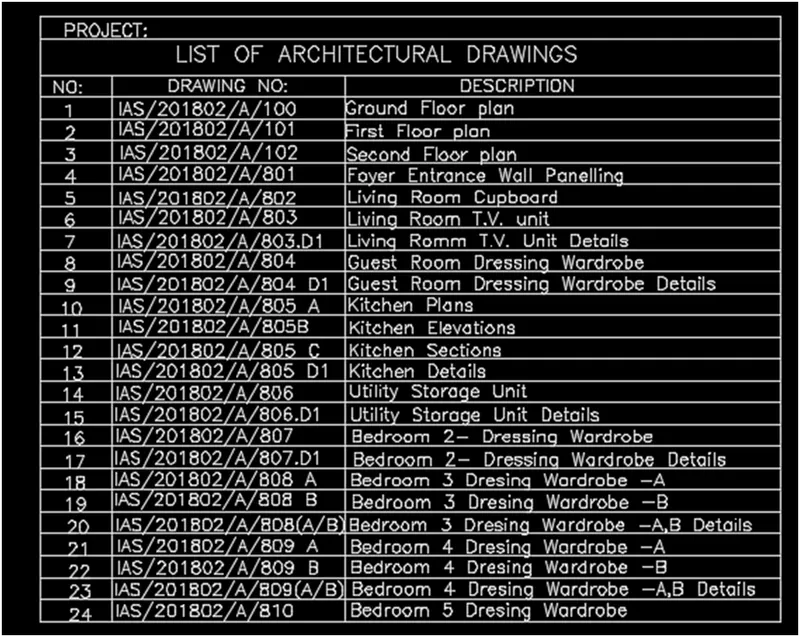
- CREATING LIST OF DRAWINGS SCHEDULE:
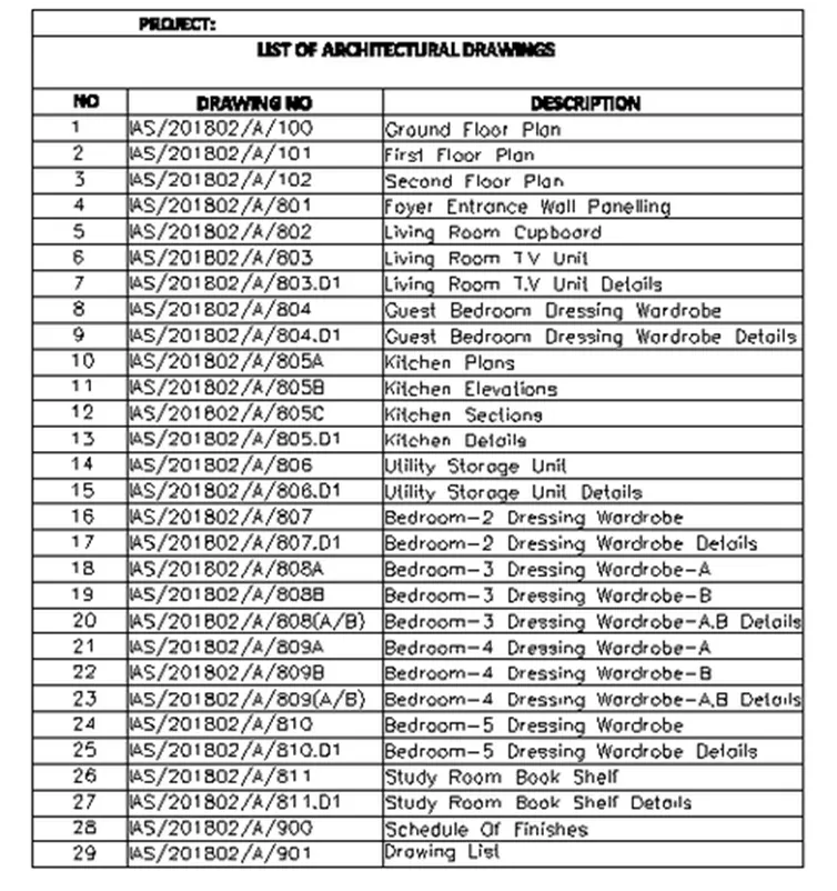
Aim: To create the list of drawings schedule
Procedure:
Step 1: Basic settings
- Open AutoCAD
- Open new drawing
- Set units (measurements as engineering, precision to 0’-0.0” , angle as decimal degree)
- Enable Ortho mode on
- Enter command dimstyle and click on modify
- Set unit to engineering and precision to 0’-0.0”
Step 2: Creating table:
- Select construction lines by using “XL” in command box
- Draw a vertical as well as horizontal line
- Use trim command and delete the bottom and left excess lines
- Select copy tool and select horizontal line (at joint)
- Select array from command box
- Move the cursor upwards
- Give a number of 33 and length as 3’
- Press enter
- Now select offset tool
- Give a length as 5’
- Select vertical line move the cursor right side and press enter
- Now select offset tool
- Give a length as 15’
- Select vertical line move the cursor right side and press enter
- Now select offset tool
- Give a length as 25’
- Select vertical line move the cursor right side and press enter
Step 3: Text
- Enter the text in the table by using single line text from the text drop down menu
- Specify the point of text specify text height as 8"
- Text angle as 0 degree,
- Now click at the selected points and enter text as given
- After entering the text, right click and select properties then list of properties will be displayed -ensure that the text height is 8" and make justify as left
- To change the style of text Command "ST, A dialogue box appears and select the font name
- Then insert all the text or copy the text created and edit it to the required text in respective rows and columns
RESULT:
- CREATING BEAM DETAILS:
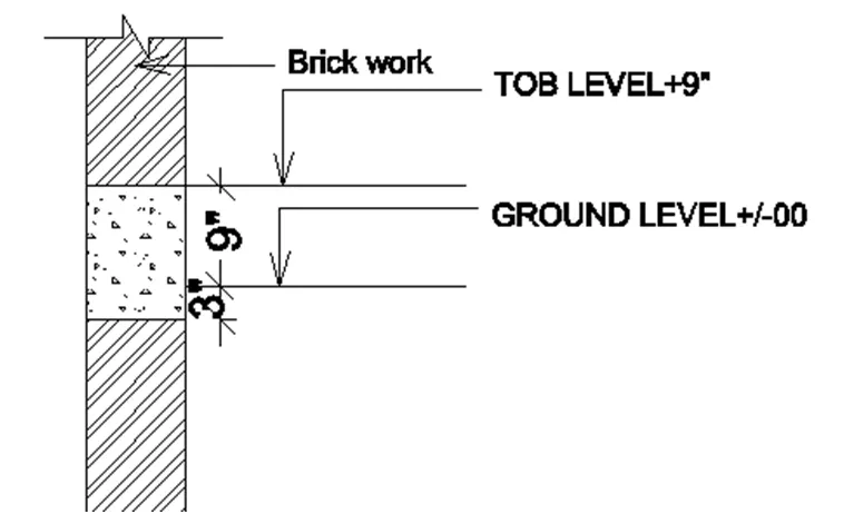
Aim: To create beam details as given in the figure
Procedure:
Step 1: Basic settings
- Open AutoCAD
- Open new drawing
- Set units (measurements as engineering, precision to 0’-0.0” , angle as decimal degree)
- Enable Ortho mode on
- Enter command dimstyle and click on modify
- Set unit to engineering and precision to 0’-0.0”
Step 2: Drawing
- Use line command to Draw the cross section of beam with height and thickness of 4’ , 9” respectively
- Select line tool from start point move the cursor right side and give a length of 9”
- Next point move the cursor up and give a length of 4’
- Next move the cursor left and give length as 9”
- Enter “c” to close the circuit
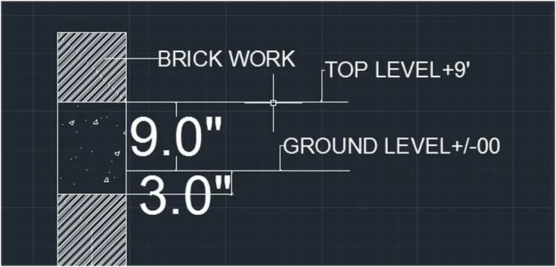
- From the top line give a offset line of 9” by using “offset tool” to form top level
- Then select offset tool and give a distance of 9” , select the TL line and move the cursor downward and press enter
- Then select offset tool and give a distance of 3” , select the bottom line and move the cursor upward and press enter to form Ground level line
- Now extend the top level and ground level lines using grips extend
- Use trim tool to trim the unwanted lines
- Hatch the portion of brick and concrete as given in fig
Step 3: Text
- Select multi learder from annotate tab and give text height of 2”
- Type “top level +9” at the top of 9” line
- Type “ground level +/00” at the top of 3” line
- Type “BRICKWORK” indicating the part of brickwork using multileader
RESULT