Creation of Column Schedule and Drawing Template using AutoCad
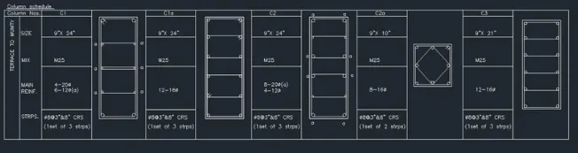
1.AIM : To create a column schedule asshown in the figure by using auto cad.
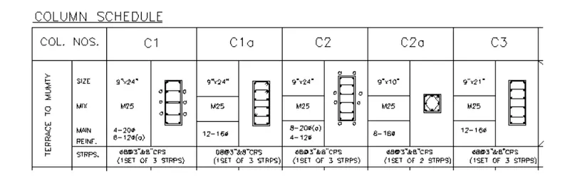
INTRODUCTION:
introduction: AutoCAD consists of a number of drawing and modification tools. Among the modification
toolss are
chamfer, fillet,offset,object snap, rotate,copy,move,mirror,trim, entend and join Chamfer: A chamfer is an angled line that meets the endpoints of two straight 2D objects its a sloped transition between two surfaces or adjacent faces on a 3D solid. We type CHA for this tool in command bar
drafting a following tools by using following commands like, by using object snap elliptical command, by using arcs commands construction lines and ray tools, divide and measure tool, and by Using modity commands like mirror, trim, entand explode, lenghten, align, break and join command, and manage layers in autoCAD 2019
Procedure:
• Get in to a new drawing file and set start up settings in to Imprerical
• Set limits as 10',10' by using LI command • Set the text height as 8" and text style as Romans.SHX
by using ST command
• Set th units in architecture
Step:1 Create a rectangle as per assumerd size which depends upon sizes of column and text.
Type rectangle in command prompt > Specify the
dimensions
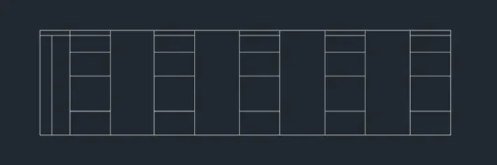
By using line command and offset command divide the rectangle in to 5 parts X direction and four parts in Y direction
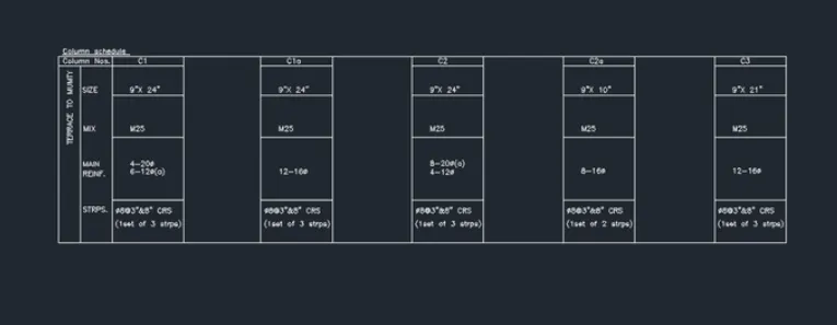
Type the text snown in figure by using DTEXT command
• Text can be rotated by using rotation command
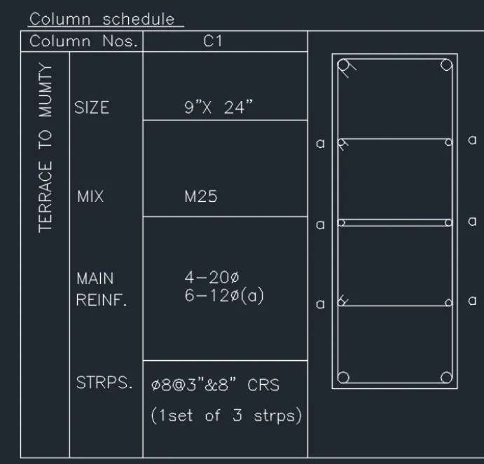
STEP:2 Draw the column details as[er dimensions
Type rectangle in Command prompt: RECTANG
Specify other corner point or
[Area/Dimensions/Rotation]:d
Specify length for rectangles: 9"
Specify width for rectangles: 24"
Command: OFFSET
• Specify offset distance: 0.4"
• Select the rectangle and in side of the rectangle
• Create a circle by using circle command and select TTR option
• Select the lines of first corner as tangents and type radius as:0.39" as (10mm radius)
• Mirror the circle at opposite & vertically downwards
direction with refrance the mid line of inner rectangle Specify the circle of radius 0.23" at a 3 points of 6' equal distance
• Mirror the circle at opposite & vertically downwards
direction with refrance the mid line of inner rectangle
• Extensions of circle can be provided by line command
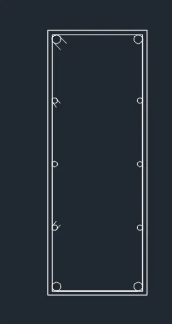
Type explode command to explode inner rectangle
and copy the line at qadrents with copy command of the circle per figure given
• By trim command trim the extension lines or by using fillet command by radius of the circle
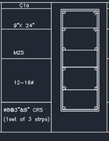
FOR C1 a:
Type rectangle in Command prompt: RECTANG • Specify other corner point or
[Area/Dimensions/Rotation]:d
Specify length for rectangles: 9
• Specify width for rectangles: 24"
Command: OFFSET
• Specify offset distance: 0.4"
• Select the rectangle and in side of the rectangle
• Create a circle by using circle command and select TTR option
• Select the lines of first corner as tangents and type radius as :0.314" as (8 mm radius)
Explode the offset rectangle and divide in to 5 equal parts by divide command
copy the circle at the divided length
• Mirror the circle by using MI command at opposite & vertically downwards direction with refrance the mid line of inner rectangle.
Offset the lines at quadrents of the circles with offset
command
Fillet the corners with radius.
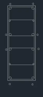
FOR C2:
Type rectangle in Command prompt: RECTANG
Specify other corner point or
[Area/Dimensions/Rotation]:d
Specify length for rectangles: 9"
Specify width for rectangles: 24" • Command: OFFSET
• Specify offset distance: 0.4"
• Select the rectangle and in side of the rectangle
Explode the inner rectangle
• Divide in to 5 parts of the inner vertical line and copy the
base line of inner rectangle at 5 parts of rectangle
Draw the circle with TTR method of 0.39" at the corners of the inner rectangle
and 0.23" at the remaining corners • Use trim command for removing extra lines.
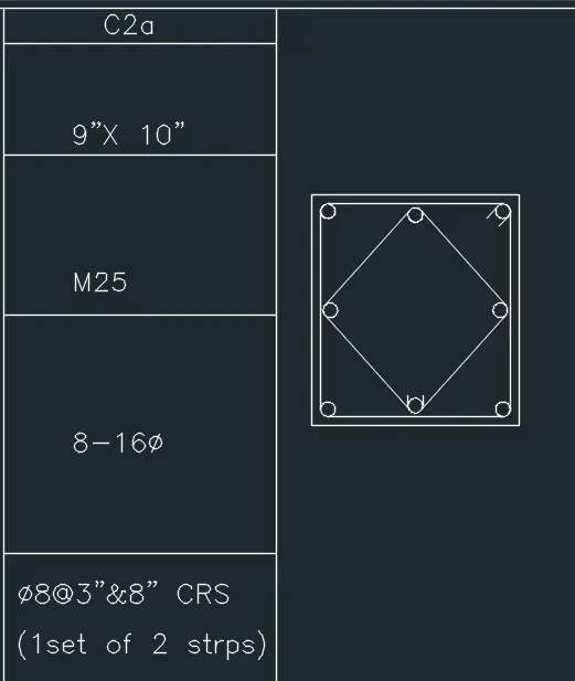
FOR C2a:
• Type rectangle in Command prompt: RECTANG
Specify other corner point or
[Area/Dimensions/Rotation]:d
• Specify length for rectangles: 9"
Specify width for rectangles: 10" • Command: OFFSET
Specify offset distance: 0.4"
Select the rectangle and in side of the rectangle
• Draw a line joining to all mid point of offset rectangle
Using circle command with radius 0.314" make a circle by TTR option for all corners at rectangle and rhombus
Use trim command for removing extra lines.
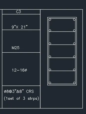
FOR C3:
Type 'rec' or rectangle in the command prompt • Specify other corner point or [ Area: Dimension:
Rotation]: D
Specify length for rectangle: Type 9" and press enter Specify width for rectangle: Type 21" and press enter
• Offset the rectangle at 0.4" Expolde the inner rectangle by explode command.
• Divide in to 5 parts by Divide command
• copy the base line of inner rectangle in to 5 points
• Draw the circle by usiong circle command with TTR
option
• Select the corner lines as the tangents and enter radius
0.314".
result:
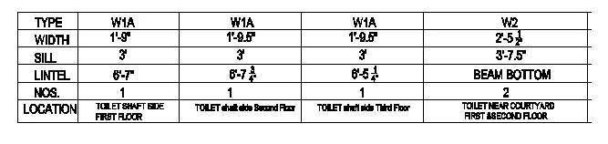
2.AIM : To create a window schedule given in the figures by using Auto Cad.Window schedule:
Procedure:
Open Drawing file
Set the units (Feet and inches)
Step 1: Creating Table using Rectangle
• Type RECTANGLE command in the command box and
press enter
• Specify the first point on the screen then second point
Explode with explode command.
And divide in to six parts from vertical and horizontal direction using divide command.

set text size 8" and texty style in roamns.SHX by using ST command.
• Type the text given in schedule by using text command.
Dtext
• For example: Dtext > rotation :0> enter text >type
set text size 8" and texty style in roamns.SHX by using ST command.
• Type the text given in schedule by using text command
Dtext
• For example: Dtext > rotation :0> enter text >type

Repete the above command to fill the text in table
Result:

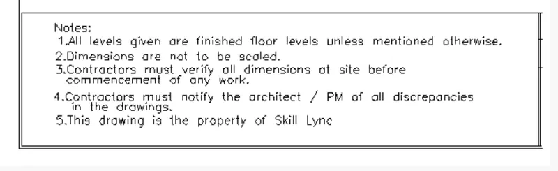
3.Aim: To create A drawing templete
procedure:
Open Drawing file
Set the units (Feet and inches)
Set the text style as Romans.SHX and text height as 8"
Step 1: Creating Table using Rectangle
• Type RECTANGLE command in the command box and press enter
• Specify the first point on the screen then second point Explode the rectangle with explode command.
type note text with multi text command
make cells in rectalgle by using line command
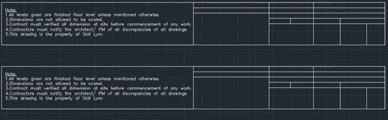
Type the text given in schedule by using text command
DText.
Result:

4.AIM : To create the list of drawing schedule by using AUTOCAD as shown in the figure.
Procedure:
• Open Drawing file:
• Set the units (Feet and inches)
Type TABLE command in command prompt
• SET NUMBER OF COLUMNS 3
• COLUMN WIDTH 1'
DATA ROW: 31
• ROW HEIGHT:1
• CLICK OK
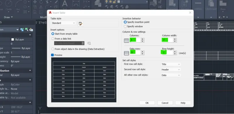
Specify the starting point
• Type the text in cells
Result:
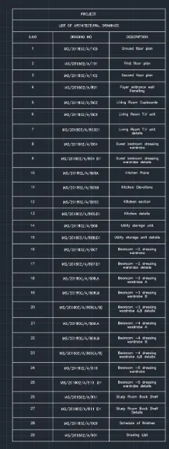
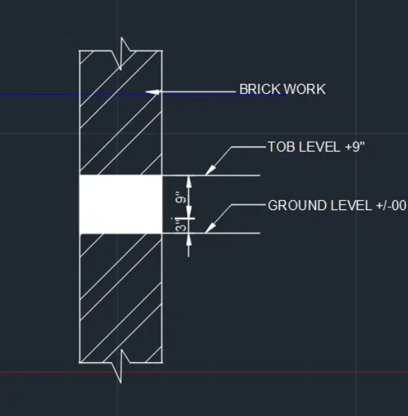
5.AIM : To create the Beam detail as shown in the figure by using AUTO CAD and provide text
wherever given.
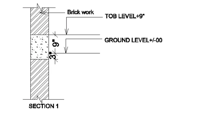
Brick work:
TOB LEVEL+9"
6
GROUND LEVEL+/-00
SECTION 1
Procedure:
• Get in to a new drawing file and set start up settings in
to Imprerical
• Set limits as 10',10' by using LI command
• Set the text height as 8" and text style as Romans.SHX
by using ST command
• Set th units in architecture
Step to follow:
• Type a RECTANGLE command in command prompt
specify first poinrt
specify dimension as 1,10'
at the middle of rectangle join with horizontal line by
using LINE command Using OFFSET command make 3" offset above the
horizontal line
and 9" to the last off set line
• Type break line command to draw the break line symbol
on top and botttom side of figure
• Apply hatch by using hatch Command and select the
closed area to hatch
Give a dimensions by dimension linear command • Provide text by LEADER command
Result:
conclusion:
ALL RESULT OF EACH DRAWING HAS BEEN ATTACHED WHICH WAS TAKEN FROM AUTOCAD