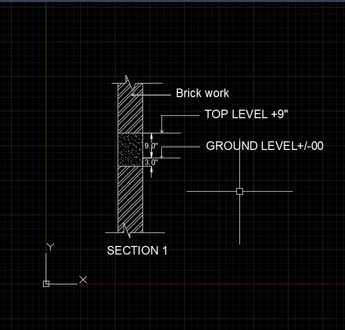
Creation of Column Schedule and Drawing Template using AutoCad
1.AIM
To create the column schedule using the various commands in Auto CAD.
PROCEDURE
- To create a new drawing sheet .
- Type ,,UN’ to set the units of current format of measure.
- Type ,,LIMITS’ to set the maximum dimension limits on the particular page.
- Type ,,L’ - Line commands allows to creating a line where the end points allows creating a line where the end points are dimensional co-ordinates.
- Type ,, OFF’ – offset command to create a new object that specified distance from an existing objects or through a specified points. ( For EX .. Rows and Column of the table.
- Type ,, Text’ to create the text ( SINGLE or MULTI ).
- Next to set up annotative options to change the Text Style of SHX.
- To select the objects goes to properties( Right click) and to change the standard required text height, scale, etec..,
- Type ,, Tr’ – Trim command is used to trims off an objects cutting the extra edges on objects.
- COPY – this commands is used to selected objects from a given square to destination, learning a copy at the originally selected location.
- ROTATE – rotate the objects around a specified point.
- MOVE – moves the objects to the destination place from the source place.
- Finally, to save the drawing file.
RESULTS
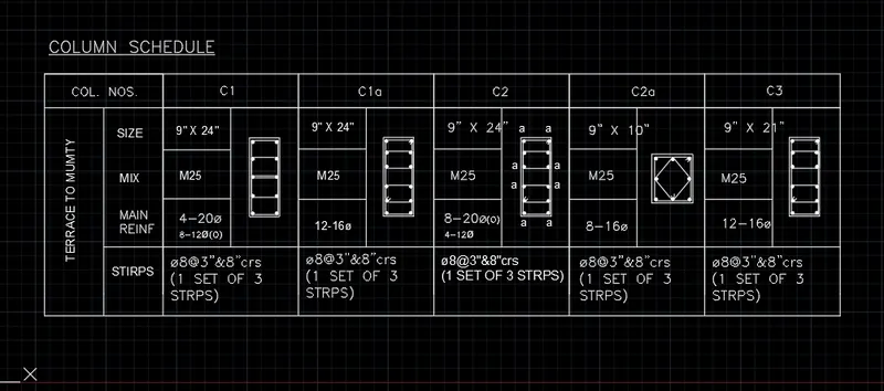
The diagram of the given column Schedule is drawn as per dimensions using the software of Auto CAD.
DIAGRAM
2.AIM
To create the window schedule using the various commands in Auto CAD.
PROCEDURE
- To create a new drawing sheet .
- Type ,,UN’ to set the units of current format of measure.
- Type ,,LIMITS’ to set the maximum dimension limits on the particular page.
- Type ,,L’ - Line commands allows to creating a line where the end points allows creating a line where the end points are dimensional co-ordinates.
- Type ,, OFF’ – offset command to create a new object that specified distance from an existing objects or through a specified points.
- Type ,, Text’ to create the text ( SINGLE or MULTI ).
- Next to set up annotative options to change the Text Style.
- To select the objects goes to properties( Right click) and to change the standard required text height, scale, etec..,
- Type ,, Tr’ – Trim command is used to trims off an objects cutting the extra edges on objects.
- COPY – this commands is used to selected objects from a given square to destination, learning a copy at the originally selected location.
- ROTATE – rotate the objects around a specified point.
- MOVE – moves the objects to the destination place from the source place.
- Finally, to save the drawing file.
RESULTS
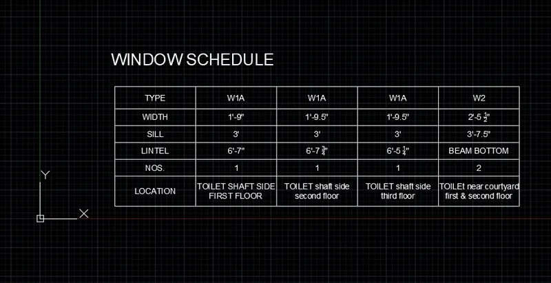
The diagram of the given window Schedule is drawn as per dimensions using the software of Auto CAD.
DIAGRAM
3..AIM
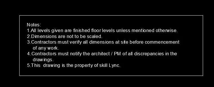
To create the drawing template using the various commands in Auto CAD.
PROCEDURE
- To create a new drawing sheet .
- Type ,,UN’ to set the units of current format of measure.
- Type ,,LIMITS’ to set the maximum dimension limits on the particular page.
- Type ,,L’ - Line commands allows to creating a line where the end points allows creating a line where the end points are dimensional co-ordinates.
- Type ,, OFF’ – offset command to create a new object that specified distance from an existing objects or through a specified points.
- Type ,, Text’ to create the text ( SINGLE or MULTI ).
- Next to set up annotative options to taken the PARAGRAPH option to write the notes of the drawing sheet.
- To select the objects goes to properties( Right click) and to change the standard required text height, scale, etec..,
- Type ,, Tr’ – Trim command is used to trims off an objects cutting the extra edges on objects.
- COPY – this commands is used to selected objects from a given square to destination, learning a copy at the originally selected location.
- MOVE – moves the objects to the destination place from the source place.
- Finally, to save the drawing file.
RESULTS
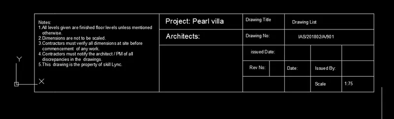
The diagram of the given drawing template is drawn as per dimensions using the software of Auto CAD.
DRAWING
4.AIM
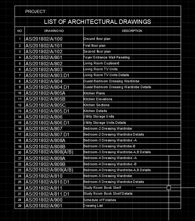
To create the List Of Drawing Schedule using the various commands in Auto CAD.
PROCEDURE
- To create a new drawing sheet .
- Type ,,UN’ to set the units of current format of measure.
- Type ,,LIMITS’ to set the maximum dimension limits on the particular page.
- Type ,,L’ - Line commands allows to creating a line where the end points allows creating a line where the end points are dimensional co-ordinates.
- Type ,, OFF’ – offset command to create a new object that specified distance from an existing objects or through a specified points.
- To choose the Annotative then prefer the TABLE option for making the column and rows.
- Type ,, Text’ to create the text ( SINGLE or MULTI ).
- Next to set up annotative options to change the Text Style
- To select the objects goes to properties( Right click) and to change the standard required text height, scale, etec..,
- Type ,, Tr’ – Trim command is used to trims off an objects cutting the extra edges on objects.
- COPY – this commands is used to selected objects from a given square to destination, learning a copy at the originally selected location.
- MOVE – moves the objects to the destination place from the source place.
- Finally, to save the drawing file.
RESULTS
The diagram of the given List Of Drawing Schedule is drawn as per dimensions using the software of Auto CAD.
DIAGRAM
5.AIM
To draw the Beam Detail using the various commands in Auto CAD.
PROCEDURE
- To create a new drawing sheet .
- Type ,,UN’ to set the units of current format of measure.
- Type ,,LIMITS’ to set the maximum dimension limits on the particular page.
- Type ,,L’ - Line commands allows to creating a line where the end points allows creating a line where the end points are dimensional co-ordinates.
- Type ,, H’ to choose the Hatch option.
- Type ,, Text’ to create the text ( SINGLE or MULTI ).
- Next to set up annotative options to change the Text Style of SHX.
- To select the objects goes to properties( Right click) and to change the standard required text height, scale, etec..,
- Type ,, Tr’ – Trim command is used to trims off an objects cutting the extra edges on objects.
- COPY – this commands is used to selected objects from a given square to destination, learning a copy at the originally selected location.
- TYPE ,,DLI’ in command bar to give the dimension of the plan.
- TYPE ,,D’ in command bar to give the size of the dimension and size of the arrows, changing tool command is DDIM.
- ROTATE – rotate the objects around a specified point.
- MOVE – moves the objects to the destination place from the source place.
- Finally, to save the drawing file.
RESULTS
The diagram of the given Beam Detail is drawn as per dimensions using the software of Auto CAD.
DIAGRAM