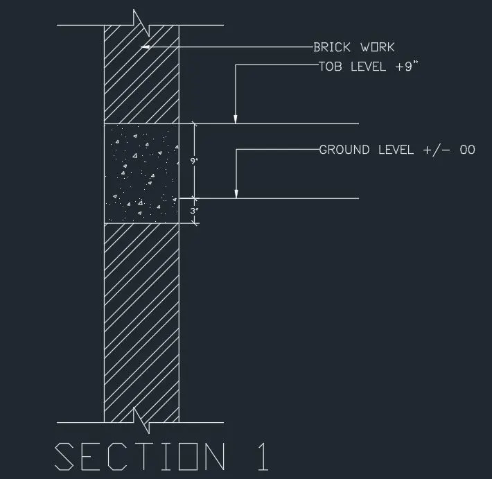
Creation of Column Schedule and Drawing Template using AutoCad
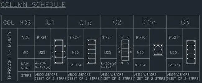
1. Column schedule :-
AIM :- Create a column schedule with the help of lines. Also, insert text with the help of Dtext command or Single Line text.
Procedure :-
- Type UNITS in the command toolbar
- Select the Engineering options and select precision as 0'-0"
- And select the Insertion scale as Inches
- Select the line tool by entering the LINE in the command tool bar
- Specify the first point as 0,0 in the command tool bar
- Specify the co-ordinate of next point as @60',0' in the command tool bar
- Specify the co-ordinate of next point as @0',20' in the command tool bar
- Specify the co-ordinate of next point as @60',0' in the command tool bar
- Click on close tool in the command tool bar
- Select the Offset tool by entering the OFFSET in the command tool bar
- Type 5' as the offset distance and select the left vertical line to be offseted
- Repeat the same of offset command 10 times
- Type 5' as the offset distance and select the top horizontal line to be offseted
- Click on the inner side of the table and click on enter button
- Select the Offset tool by entering the OFFSET in the command tool bar
- Type 3' as the offset distance and select the Bottom horizontal line to be offseted and press enter inside the table
- Select the previous line that should be offset and type 4' as the offset distance
- Repeat the same of offset command 2 times
- Select the Trim tool by entering the TRIM in the command tool bar
- by selecting trim tool trim the unwanted lines
- Press Esc to cancel the trim command
- Enter ST command in tab for the text style
- Select the romans.shx as the default font and 8" as the text height
- Enter the DTEXT in the command tool bar
- specify th start point and give the angle of rotation as 0
- Give all necessary Dimensions and text as per requirements in the Column Schedule
- Now create Column 1(C1),
- Select the rectangle tool by entering the RECTANG in the command tool bar
- Select the start point where you can draw the C1
- Select the Length as 9" and Width as 24" and move the cursor on the upward direction
- Select the Offset tool by entering the OFFSET in the command tool bar
- Type the 1" as offset distance in the command tool bar
- Press Esc to cancel the offset command
- Click on the rectangle to select it and click inside the rectanglee
- Select the Circle tool by entering the Circle in the command tool bar
- Specify the centre and radius as 0.5"
- create the another circle of 0.3" and placed it in desired location
- Select the fillet tool by entering the Fillet in the command tool bar
- Fillet the corners of inside rectangle by selecting the radius as 0.5"
- And also fillet all corner of the inside rectangle
- Select the line tool by entering the LINE in the command tool bar
- draw the stirrups by line tool press Esc to cancel the line tool
- After that Select dtext tool by entering the DTEXT in the command tool bar
- Highlights the bars and press Esc
- Draw C1a, C2, C2a, C3 by the above method and as per requirements in the column Schedule
- Copy all the columns and placed in the table at desired loacations
- And finally save the drawing
RESULT :-
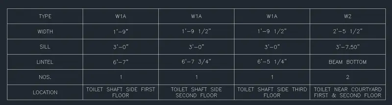
2. Window schedule :-
AIM :- To Create a window schedule
Procedure :-
- Enter UNITS command in the command tool bar.
- In the Drawing Units dialog box, select Arcitectural' in Type ' 0'-1/4"' in Precision; and Inches in Insertion scale.
- Click on Ok.
- Enter TABLE command in the command prompt
- In the Insert Table dialog box, specify the number of columns as 5 and column width as 5 similarly specify the number of rows as 6 and row height as 5.
- Click OK.
- Enter ST command in the command tab to open the Text Style dialog box.
- Select the Font Name as romans.shx Text Height as 10”.
- Enter MTEXT command in the command line.
- Specify the start point of text as required.
- Create the text box.
- Type in the required text and Press Enter.
- Scale the text to the desired size.
- Enter 'CO' command in the command line.
- Select a text and copy it to the desider locations.
- Pre Esc to cancel the copy command.
- And finally Save the drawing
RESULT :-
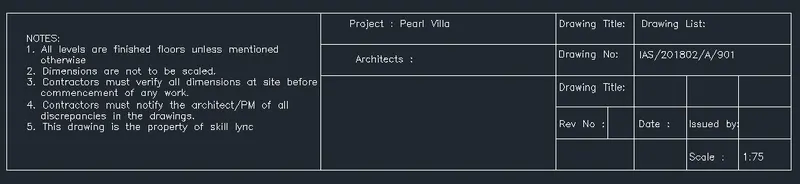
3. Drawing template :-
AIM :- To Create a drawing template
Procedure :-
- Enter UNITS command in the command tab.
- In the Drawing Units dialog box, select Arcitectural in Type; 0'-0" in Precision and Inches in Insertion scale & Click on OK.
- Select the Rectangle tool by entering REC command in the command tab.
- Specify the first point of the rectangle.
- Select Dimensions option in the command line.
- Specify length of rectangle as 100' and width as 20' in the command tool bar
- click on the Explode icon on the explode the rectangle that previous created
- Select the Offset tool by entering OFFSET command in the command tab.
- Specify offset distance as 40' and press enter.
- offset again,specify a distance of 30', select the previous offsetted line and click on that side a per requirement
- offset, specify a distance of 10', select the previous offsetted line and click towards right side to create the third column.
- Repeat offset, specify a distance of 6'8" select the previous offsetted lineand click towards right side to create the fourth column.
- Repeat offset, specify a distance of 6'8" select the previous offsetted line and click towards right side to create the fifth and sixth column.
- Repeat offset, specify a distance of 4' select the top horizontal line and click downwards to create the first row, repeat the same 4 more times to create all the rows.
- Repeat the offset command.
- Enter 2" as offset distance in the command line.
- Select the left edge of the table and specify a point to offset to create boder line for the table.
- Repeat offset for all boderline.
- Press Esc to cancel the Offset command.
- Press Esc to cancel the OFFSET command.
- Select the Trim tool by entering TR command in the command tab.
- Press ENTER.
- Select Edge option; and click on No Extend.
- Select the unwanted lines to trim.
- Press Esc to cancel the TRIM command.
- Enter ST command in the command tab to open the Text Style dialog box.
- Select the Font Name as romans.shx Text Height as 10”.
- Enter MTEXT command in the command line.
- And type the all text as per the requirements in the drawing
- And finally save the drawing
RESULT :-
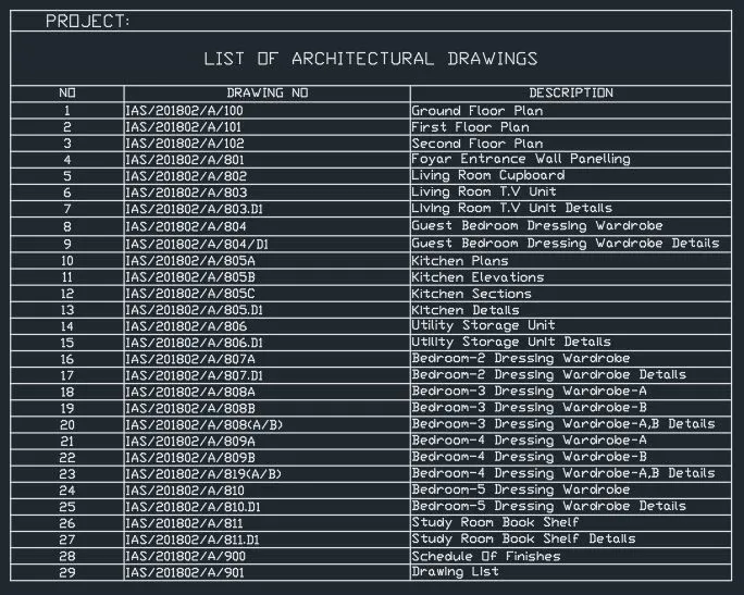
4. List of drawing scheduled :-
AIM :- To Create the list of drawing
Procedure :-
- Enter UNITS command in the command tool bar.
- In the Drawing Units dialog box, select Arcitectural in Type; 0'-0" in Precision and Inches in Insertion scale.and Click on OK.
- Enter TABLE command in the command prompt.
- In the Insert Table , specify the number of columns as 3 and column width as 5'
- Specify the number of rows as 30 and row height as 1.
- And then Click OK.
- Enter ST command in the command tab to open the Text Style dialog box.
- Select the Font Name as romans.shx Text Height as 10”.
- Enter MTEXT command in the command line.
- And type the all text as per the requirements in the drawing
- And finally save the drawing
RESULT :-
5. Beam details :-
AIM :- To Create beam details
Procedure :-
- Enter UNITS command in the command tool bar.
- In the Drawing Units dialog box, select Engineering in Type 0'-0" in Precision; and Inches in Insertion scale.
- And then Click on 'OK'.
- Select the Line tool by entering LINE command in the command tool bar.
- Specify the first point as 0,0 in the command tool bar
- Specify the coordinate of next point as @0',4' in the command tool bar.
- Specify the coordinate of next point as @9",0' in the command tool bar
- Specify the coordinate of next point as @0',-4' in the command tool bar
- Click Close on the command tool bar
- Select the Offset tool by entering OFFSET command in the command tab.
- type 1' as offset distance in the command line.
- Select the top horizontal line of the above drawing.
- Specify the point on the downward side of the line to offset.
- Extend the previous offsetted line.
- specify a distance of 9", and click downwards
- specify a distance of 3", and click downwards
- Press Esc to cancel the offset command
- Select the Line tool by entering LINE command in the command tool bar
- Draw the lines to join the cut edges of the wall section.
- Press 'Esc' to cancel the Line tool.
- Select hatching option and select the Steel and concrete hatch and click it where it was
- Enter ST command in the command tab to open the Text Style dialog box.
- Select the Font Name as romans.shx Text Height as 13”.
- Enter MTEXT command in the command line.
- And type the all text as per the requirements in the drawing
- And finally save the drawing
RESULT :-