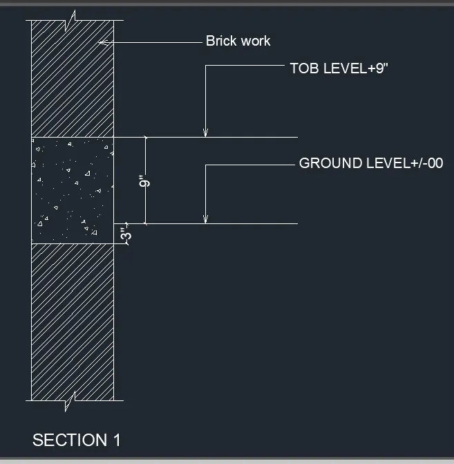
Creation of Column Schedule and Drawing Template using AutoCad
1.Create a column schedule
Aim: To create a column schedule as shown in the figure.
Introduction: To create a column schedule in Autocad by using Lines, Text, Dtext or Single line text.
Procedure:
- First we need to adjust text size and font name as given in the question.
- First we need to understand the table and at which step we need to start the table.
- Then draw the table by using line command for the first outer portion.
- Then Divide the inner lines by using offset at a certain distance of by using line also you can draw the lines.
- Now at the Bottom of the lines trim the lines as per our requirement and draw the table as shown in below drawing.
-
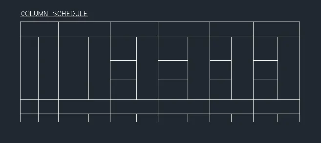
- Now table is completed, Then there is another part is reinforcement which is inserted in the table.
- For drawing of reinforcement, Take the rectangle by own dimensions and do the offset for the rectangle.
- Then draw the reinforcement bars by using circle command and do hatch for the circle, then reinforcement bars are ready.
- Now insert reinforcement bars in the rectangle and by using line command draw the lines.
- Now Reinforcement bars are ready to insert in the table as shown in below drawing.
-
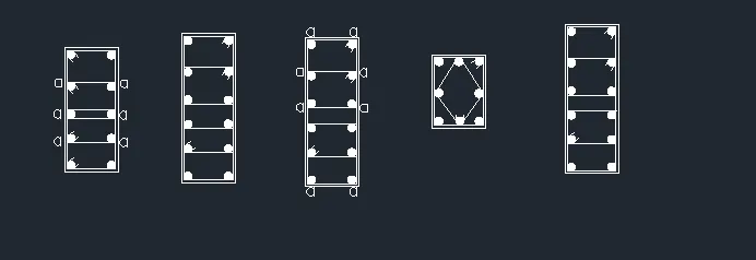
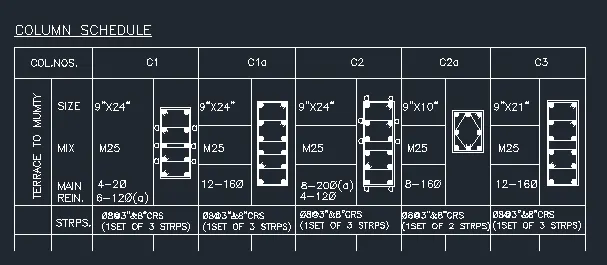
- Now Table and reinforcement is ready, Then we need to adjust in the table.
- Adjust reinforcement bars in the table with proper adjustment.
- By using text command, mention the text in the table and assign the text as shown in the table.
- Now insert reinforcement and text as shown in the figure as shown in result drawing.
Result:
2. Create a window schedule
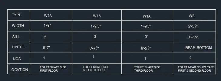
Aim:- To create a window schedule as shown in the figure.
Introduction: To create a window schedule by using schedule in Autocad by using Lines, Text, Dtext or Single line text.
Procedure:
- First we need to understand the table and at which step we need to start the table.
- Then draw the table by using line command for the first outer portion.
- Then Divide the inner lines by using offset at a certain distance of by using line also you can draw the lines.
- Now at the Bottom of the lines trim the lines as per our requirement and draw the table as shown in below drawing.
- After completing table, Now by using text command we have to insert the text as shown in the figure.
- If there is any particular size for size and font name we have to write the text in that format only, or else we can assume it.
- Take Mtext command and insert the text in all columns and rows by the data which is given in the table.
- In the given data, text is in bold letters, so text should be in bold letters only.
- Now at the last check the text sixe and height of the text which is clearly visible after inserting in the table.
- Finally the table is ready as attached in the result.
Result:
3.
Aim: To create the drawing template as in the given attachement.
Introduction: To create a drawing template in Autocad by using Lines, Text, Dtext or Single line text.
Procedure:
- If there is any particular size for size and font name we have to write the text in that format only, or else we can assume it.
- First we need to understand the table and at which step we need to start the table.
- Then draw the table by using line command for the first outer portion.
- Then Divide the inner lines by using offset at a certain distance of by using line also you can draw the lines.
- Now at the Bottom of the lines trim the lines as per our requirement and draw the table as shown in below drawing.
-
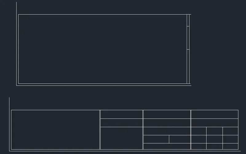
- Then we have completed the tables, now by using text command we have to insert text in the table.
- For the Top table, take the text command with font size in romans.hxt as shown in the attachment.
- By using the font which is given in the table, we have to assume the text height.
- As shown in the below drawing, text is inserted in the first table.
-
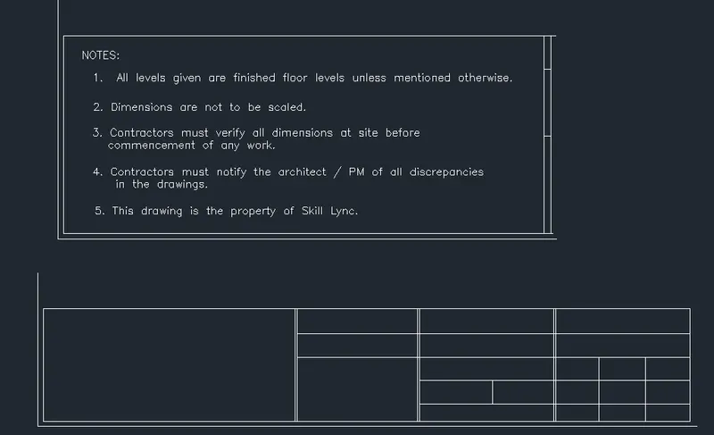
- Now for the second table also, we have to adjust the text as shown in the attachement.
- Divide the table as shown in the attached drawing, then it is easy to insert the text in the table.
- After creating the table, adjust the text height with the table and insert all the text.
- This table is used for showing the drawing details for the engineer to execute in the construction.
- Final table is ready and attached in the result as shown in the attachment.
Result:
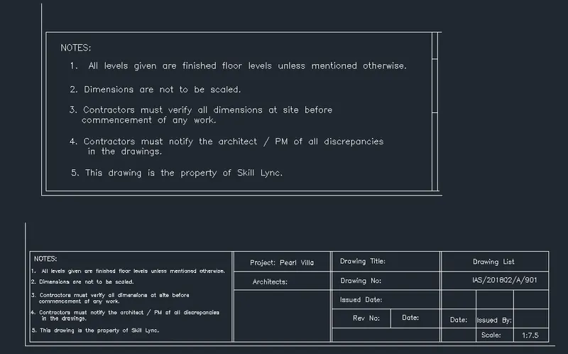
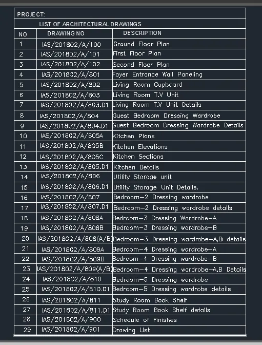
4. Create the list of drawing schedule as shown in the figure.
Aim: To Create the list of drawing schedule.
Introduction: To create a list of drawing schedule in Autocad by using Lines, Text, Dtext or Single line text.
Procedure:
- If there is any particular size for size and font name we have to write the text in that format only, or else we can assume it.
- First we need to understand the table and at which step we need to start the table.
- Then draw the table by using line command for the first outer portion.
- Then Divide the inner lines by using offset at a certain distance of by using line also you can draw the lines.
- Now at the Bottom of the lines trim the lines as per our requirement and draw the table as shown in below drawing.
-

- Now for the second table also, we have to adjust the text as shown in the attachement.
- Divide the table as shown in the attached drawing, then it is easy to insert the text in the table.
- After creating the table, adjust the text height with the table and insert all the text.
- This table is used for showing the drawing details for the engineer to execute in the construction.
- Final table is ready and attached in the result as shown in the attachment.
Result:
5. Create the Beam detail as shown in the figure and provide text wherever given.
Aim: To Create the Beam details as shown in the figure and provide text wherever given.
Introduction: To create the Beam detail in Autocad by using Lines, Text, Dtext or Single line text.
Procedure:
- First adjust the units, dimension text and font size as pe the requirement to draw the drawing.
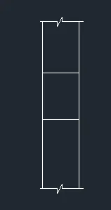
- Next by using line line command, draw the vertical lines by assuming the dimensions.
- In this drawing, there is no particular given in the some areas, so we have to assume the dimensions.
- Take the pline command, and draw the horizantal line closing the vertical lines.
- Now draw the line by dividing some portion for concrete level as shown below.
-
- Now after drawing the lines, hatch the portion of concrete level by using hatch option.
- Then hatch the portion by Ar-conc in the drawing to show the concrete filling portion.
- Next show the grond level, Tob level with the given dimensions as shown in the drawing.
- The remaining portion after concrete level should be hatched with the brick work.
- By using hatch command we have to show the brick work portion in the drawing.
- Then show the dimensions by using dimlines dimensions command.
- Then by using text show the levels and brick work where mentioned in the dawing.
- Then the final drawing is ready as shown in the result.
Result: