Creation of Column Schedule and Drawing Template using AutoCad
Question 1)
Answer-
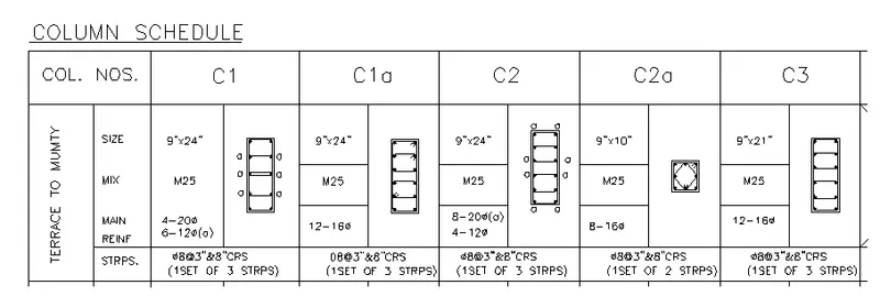
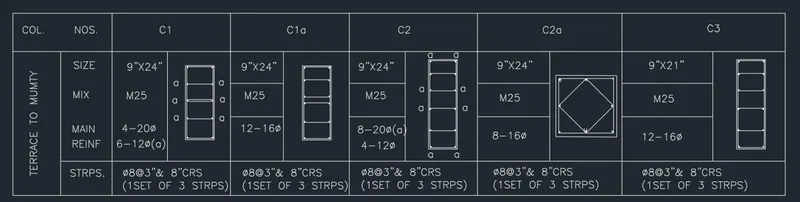
Aim: To Create a column schedule as shown in drawing by using autocad
Introduction: We have to create a column schedule given in challenge by using various command with assuming dimension.
The purpose of column schedule is a schedule which gives details of column will be collected in construction for design purpose.
Procedure:
STEP-1:
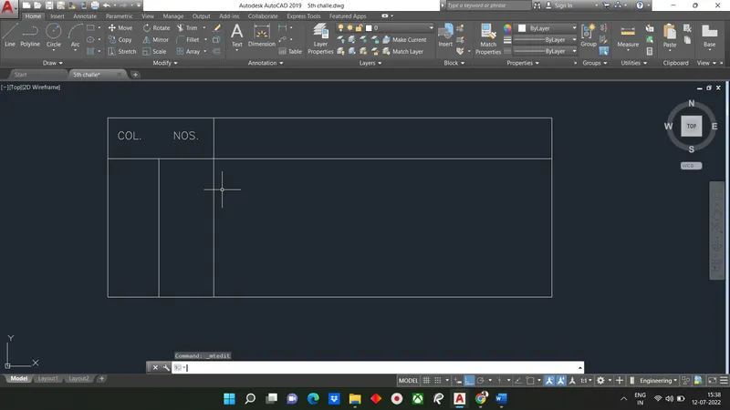
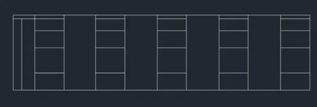
- Create new drawing in autocad & set up limits
- Create a rectangle as per assumed size which depend upon size of column and text
- Type rec in Command tab-Specify Dimension
- By using line command and offset command divide rectangle into 5 part in x direction and four parts in y direction
STEP-2:
- Type rec in command :REC
- Specify corner point with dimension give length 9" and width 24" for rectangle
- Command offset(o)
- Give offset distance 0.4"
- Select rectangle and in side of rectangle
- Create circel by using command
- Select lines of first corner as tangent and type radius 0.39"
- Mirror the circle using MI command opposide & vertical side with reference line
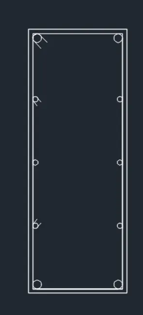
- By using trim the extension lines
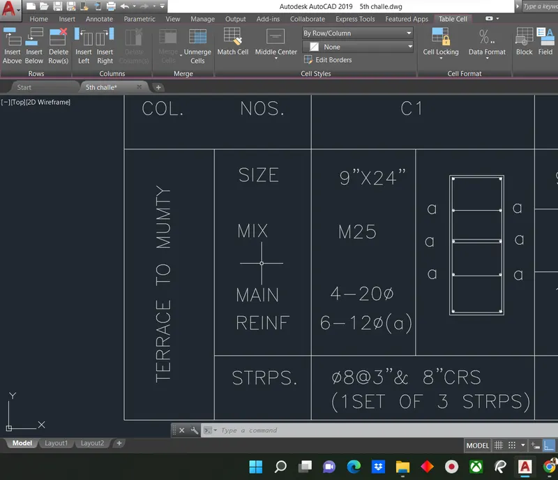
STEP-3: Do same procedure to create column detail drawing
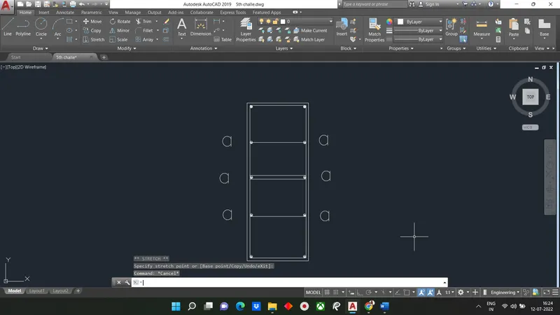
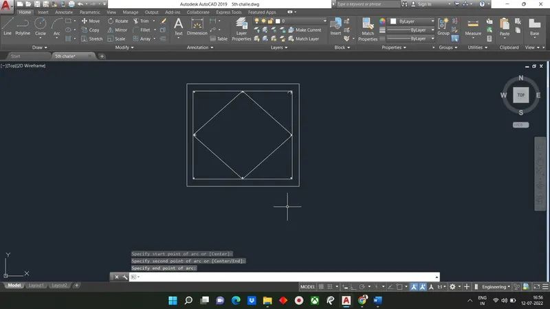
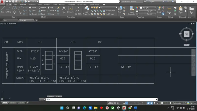
Screenshot : Using Font Roman & Text size: 8 "
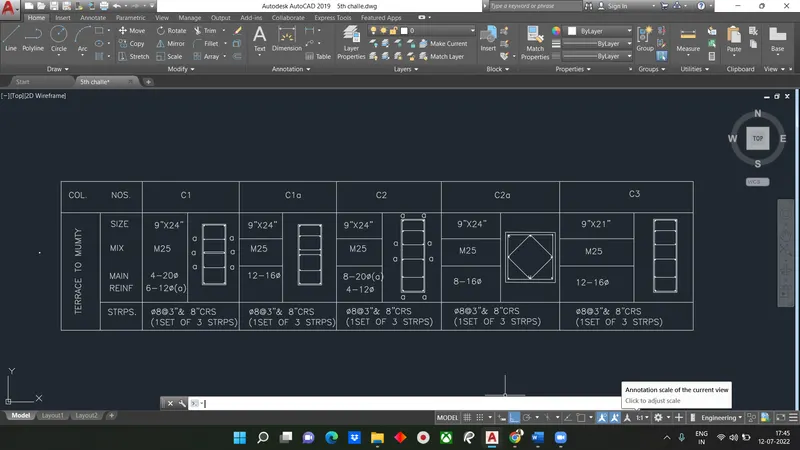
RESULT:
Question 2)
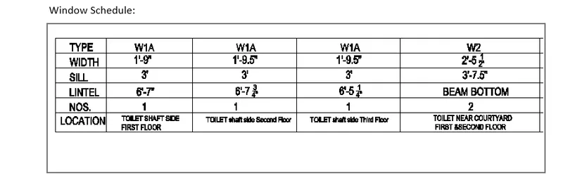
Answer:
Aim: To create a window schedule, and to draw the details of windows for construction purpose
Introduction:
The window schedule and do draw the details of the windows in construction can be collected in the table form.
Using table, circle, line, rectangle command
Procedure:
STEP-1:
- First of all we have to open autocad and set limits and units
- Next we have to draw table using line command or by writing table in command tab
Screenshot 1: Creating table to draw out window schedule
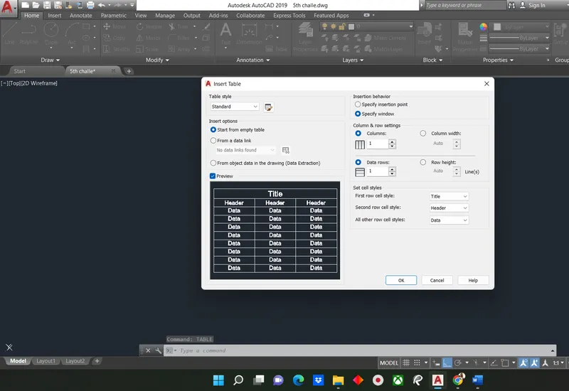
Screenshot-2: Created table we can add or delete row/column '

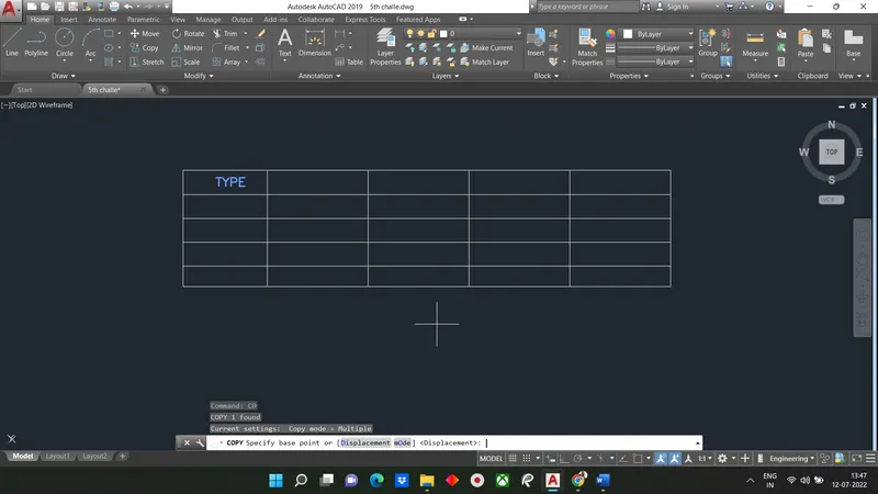
Screenshot -3: We have selected font- Romans & text height as per given
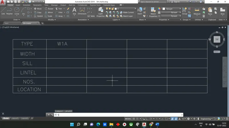
Screenshot-4: We are adding notes/information as per given in question
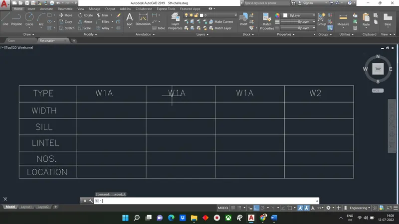
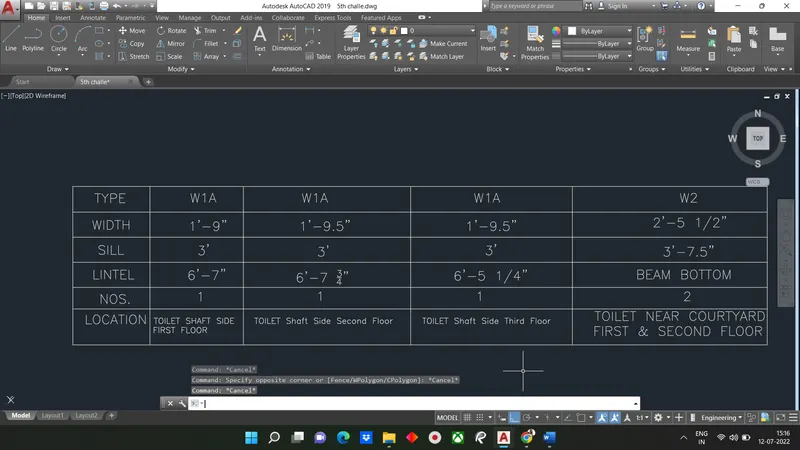
Screenshot-5: We write all the information given in window create so window schedule is created
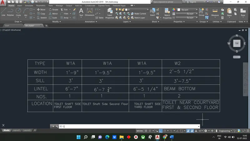
RESULT:
Question 3)
Answer-
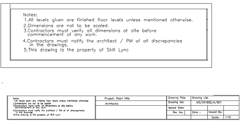
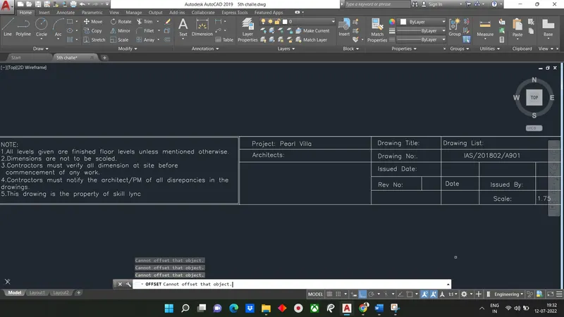
Aim: Create the drawing template as shown in the figure of Note:
Introduction: In order to create a drawing template using Dtext or text command to write text
Drawing template files are drawings that store styles, settings, layers and layouts in a drawing including title blocks.
Use Font :Roman, Height: 8"
Procedure:
Command Use-
- Limits
- Text
- Line
STEP-1:
- First off all we have to open autocad and set the limits and units
- Next we have to draw the table using the line command as shown in below table
- We draw this table for the entering details of the entire project before submitting to the client.
- After entering the details of we can submit drawing to client.
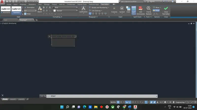
Screenshot 1-Shows Text & text height
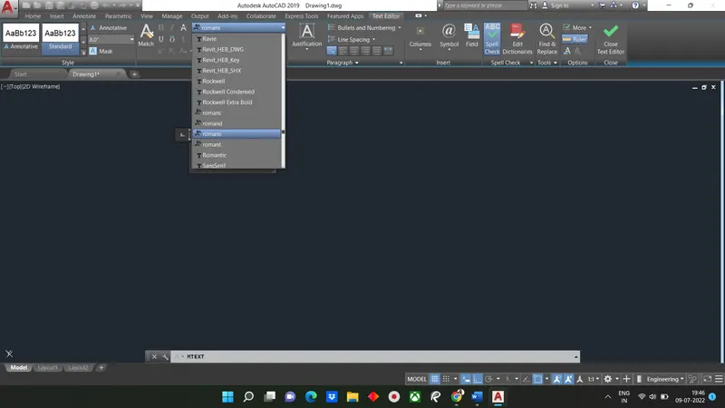
Screenshot 2-Here we add font: Roman given in question
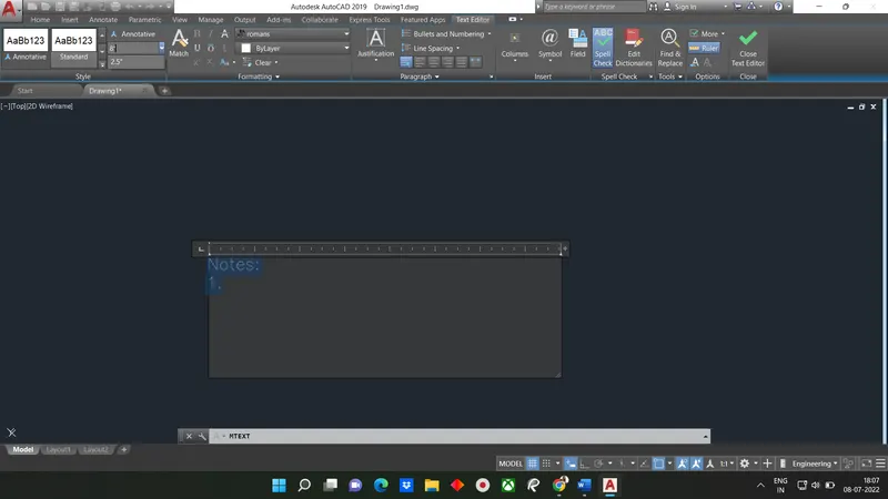
Screenshot 3: Start to write which ever is given in notes
STEP-2:
- After drawing table we have to select the Mtext command to enter the notes and project details.
- And text height will be kept it 8", and it is standard text height for entering the details of the project in table
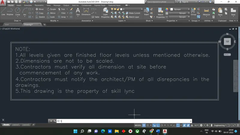
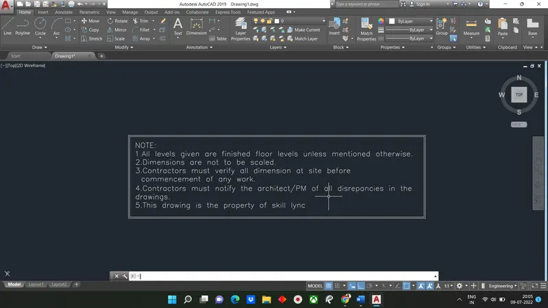
After that we write all the thing which are given in drawing template
Screenshot: Using Line(L) , trim & extend command we make drawing box/table
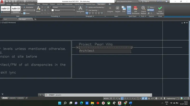
Screenshot- We have write given information using Font: Romans and size 8"
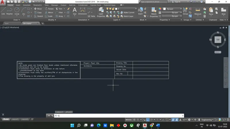
RESULT:
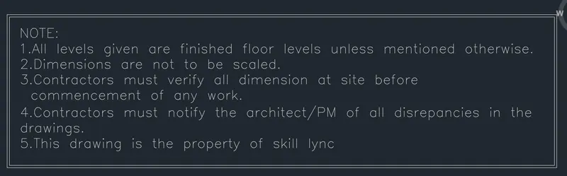 '
'

Question 4)
Answer:
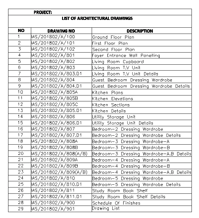
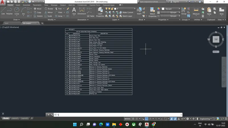
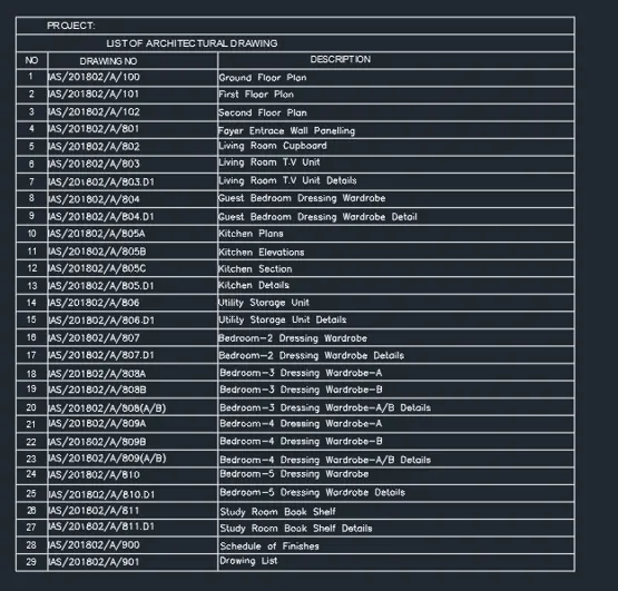
Aim: To create the list of drawing schedule as shown in figure
Introduction: A schedule of drawing is an itemised list of drawings requiredfor a building project.It can be included as part of an invitation to tender, or may be prepared as part of a design management plan.A schedule of drawings required may include all the drawings required for a project or an larger, more complex projects, It may be specifically prepared for a certain displine.
Procedure:
STEP-1:
- First we have to open Autocad and set limits and units.
- Then we have to enter table in command for creating table
- After entering table command table setting screen will be displayed as shown in screenshot 1
Screenshot-2: Creating table
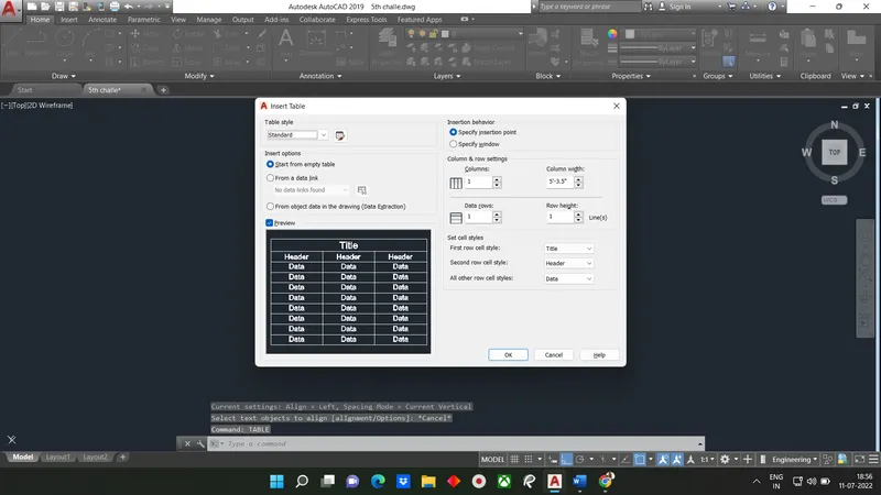
Screenshot-3: We have customized table as per required rows and column
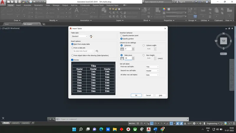
Screenshot-4:We have created table
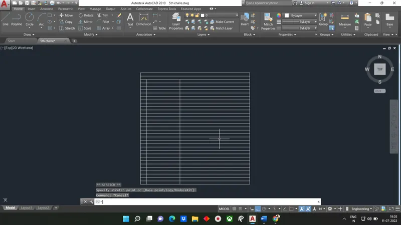
Screenshot-5: We have started to write drawing schedule with Roman font & height
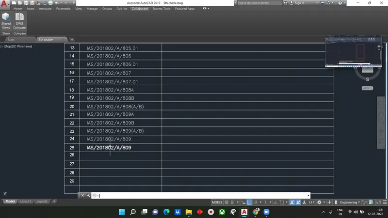
Screenshot-6: We justify it to left
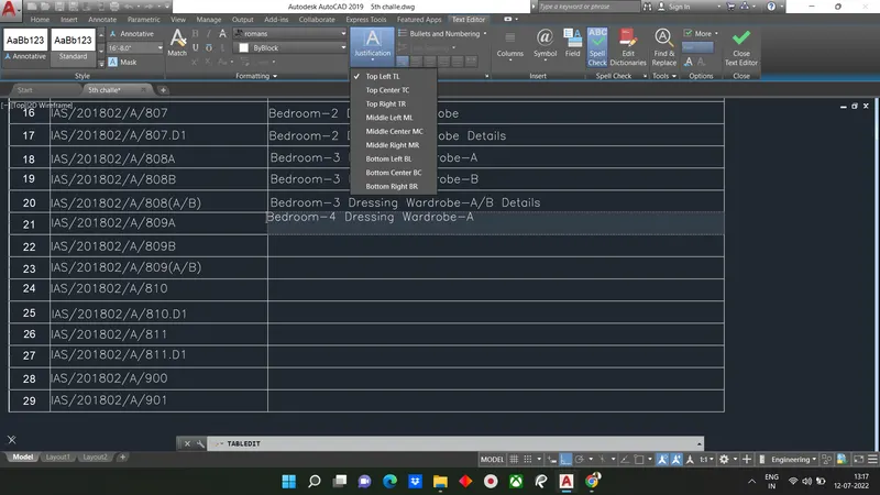
Screenshot-7: All the drawing detail are feeded
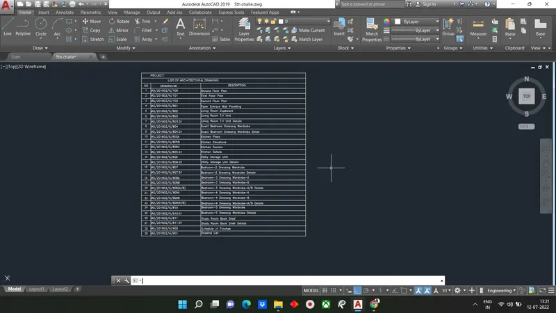
RESULT:
Question 5)
Answer
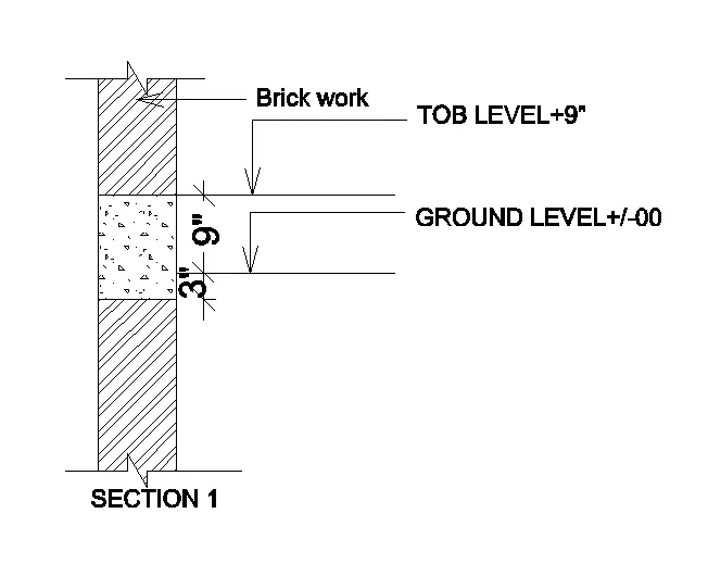
Aim: To create a beam detail given in figure
Introduction: A beam is a structural element that primarily resists load applied laterally to the beam's axis.Its mode of deflection is primarily by bending.The loads applied to the beam result in reaction forces at the beams support points.The total effect of all the forces acting on the beam is to produce shear forces and bending moments within the beams.
Command Used:
Limits
Line
Dimlinear
Trim
Offset
Procedure:
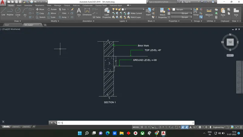
assumed dimension for beam detail
STEP-1
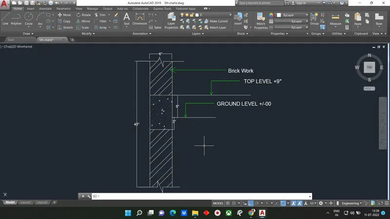
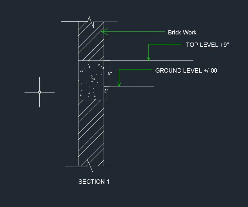
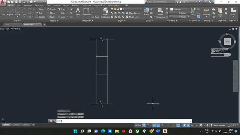
- Make two parallel lines 45" long at a distance of 6" from each other.
- Using the breakline command, make a breakline at top and bottom
- Make the horizontal lines with 9" distance and draw a line horizontally forward from that distance, that line we call the top level.
- Next we have to put the dimensions for the ground level, its distance is 3"
STEP-2
- Then next we have to provide the texts for the particular parts, they are brick work, label as Top Level and Ground Level
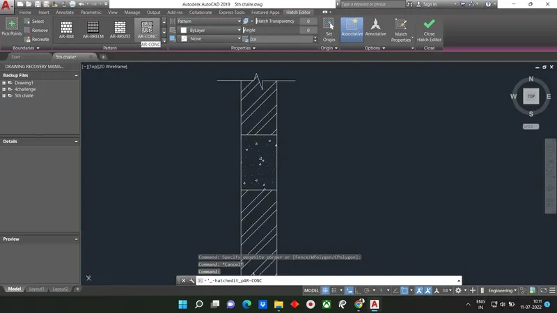
- Next we have to use hatch command to hatch the different parts in diagram
RESULT: