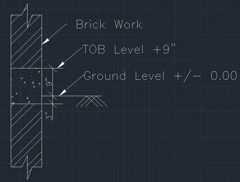
Creation of Column Schedule and Drawing Template using AutoCad
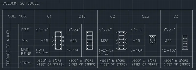
1) Aim: To create a column schedule as shown by using specified text style.
Procedure:
- Open Auto cad and open new drawing.
- Type ‘LIMITS’ in command bar and set the sheet limit as per drawing.
- Type ‘UNITS’ in command bar and set the unit type as Decimal and unit in inches set precision as required for drawing.
- Keep ortho on so that the lines move only in Right angles.
- Using Rectangular command draw a outer box. After roughly calculating the spacing needed.
- Complete all the tabular column inner part by line command and start with the column naming.
- Set the text font type as mentioned above in Dimension setting.
- Type the size naming and other using Mtext command.
- Use the required size of font.
- Draw the column layout showing the type and no. of stirrups.
- To show the thickness of the column vertical rods use Donut command.
- Select Donut and give internal dia as 0 and then external dia as required.
- By this we will get the solid circle, place the circle where required.
- For the other circle point’s use divide command and place the solid circle there.
- Make sure that the drawing and text is clearly visible for reference.
Result:
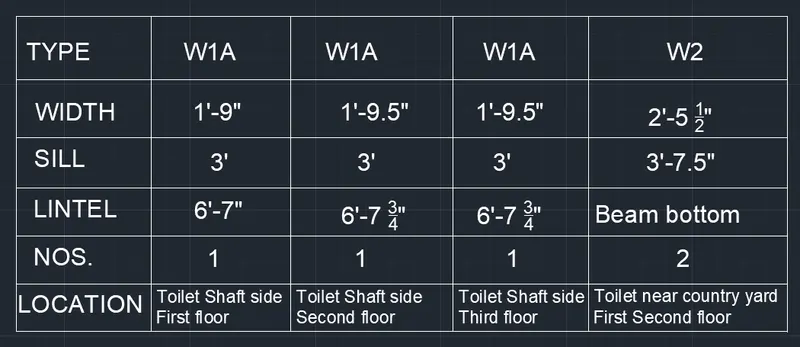
2) Aim: To create a window schedule as shown.
Procedure:
- Open Auto cad and open new drawing.
- Type ‘LIMITS’ in command bar and set the sheet limit as per drawing.
- Type ‘UNITS’ in command bar and set the unit type as Decimal and unit in meter set precision as required for drawing.
- Keep ortho on so that the lines move only in Right angles.
- Using Rectangular command draw a outer box.
- Using line command draw lines in a format of table which has 5 Columns and 6 Rows.
- Using Mtext type the given Naming and dimensions.
- Adjust the size of text with respect to the drawing so that the text is clearly visible.
Result:
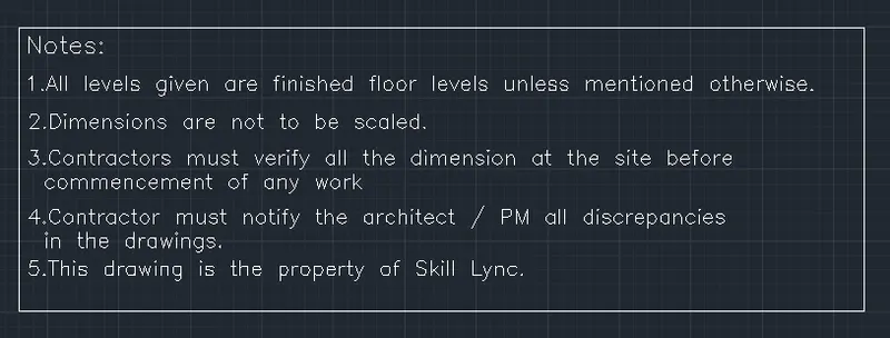
3) Aim: To create the drawing template as shown
Procedure:
- Open Auto cad and open new drawing.
- Type ‘LIMITS’ in command bar and set the sheet limit as per drawing.
- Type ‘UNITS’ in command bar and set the unit type as Decimal and unit in meter set precision as required for drawing.
- Keep ortho on so that the lines move only in Right angles.
- Using Rectangular command draw a outer box.
- Draw all the inner boxes using the line command.
- Trim off all the extra lines.
- Now using the Mtext command edit or type the given statement and naming.
- Do this with appropriate text size so that are clearly visible.
Result:

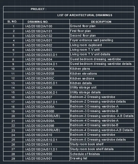
4) Aim: To create the list of drawing schedule.
Procedure:
- Open Auto cad and open new drawing.
- Type ‘LIMITS’ in command bar and set the sheet limit as per drawing.
- Type ‘UNITS’ in command bar and set the unit type as Decimal and unit in meter set precision as required for drawing.
- Keep ortho on so that the lines move only in Right angles.
- Using Rectangular command draw a outer box.
- Draw all the inner boxes using the line command.
- Trim off all the extra lines.
- Now using the Mtext command edit or type the given details.
- Do this with appropriate text size so that are clearly visible.
- Carefully see the drawing numbers and naming while entering.
Result:
5) Aim: To create the Beam detail as shown.
Procedure:
- Open Auto cad and open new drawing.
- Type ‘LIMITS’ in command bar and set the sheet limit as per drawing.
- Type ‘UNITS’ in command bar and set the unit type as Decimal and unit in inches set precision as required for drawing.
- Keep ortho on so that the lines move only in Right angles.
- Using line command, draw the outer line anywhere in the screen.
- Using offset command, draw the thickness of wall and beam.
- Trim off all the extra lines.
- Do the hatching of wall and concrete using hatch command.
- Adjust the size or scale of the hatch so that it is visible.
- Using the dimension show the sizes of the beam.
- Select MLeader or Leader for the naming purpose.
- Do the naming as given and also adjust the size as per visibility.
Result: