Creation of Column Schedule and Drawing Template using AutoCad
DRAWING 1:
AIM:
To create a column schedule as shown in figure
INTRODUCTION:
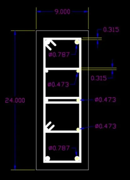
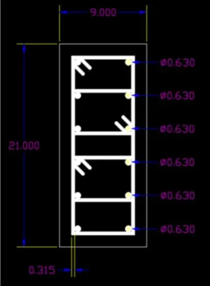
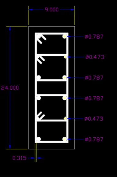
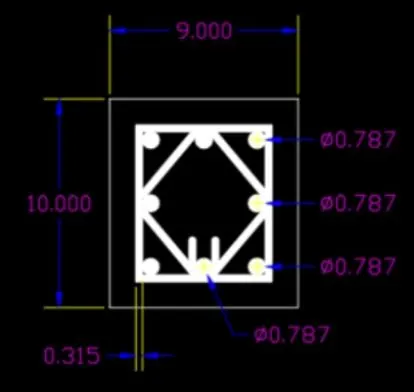
Columns (C1, C1a, C2, C2a, C3) is created using AutoCAD and create a tabular column
PROCEDURE:
Open AutoCAD set units and limits
Convert dia of bars from mm to inches
| mm |
inches |
| 20 | 0.7874 |
| 16 | 0.6259 |
| 12 | 0.4725 |
| 8 | 0.3150 |
DRAWING C1:
DRAWING C1a:
DRAWING C2:
DRAWING C2a:
DRAWING C3:
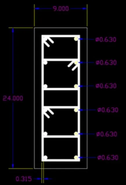
1.In command box type line and create a tabular column as given
2.Now type ST>romans.shx>8" (height) >left
3.Type text command to insert text in required boxes
4.now type MTEXT (multiline text) > symbols > to get diameter symbol.
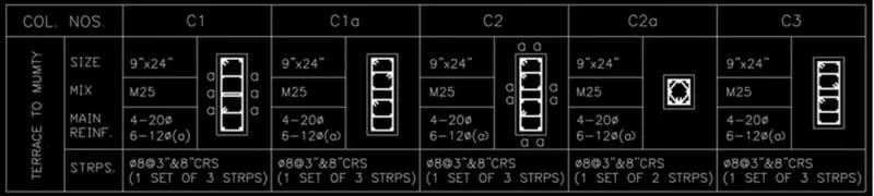
RESULT:
The column schedule has been created using AutoCAD.
DRAWING 2:
AIM:
To create a window schedule as shown in the figure
INTRODUCTION:
The table contains the width, sill level, Lintel, Nos, and Location for different types of beam
PROCEDURE:
1.In command box type line and create a tabular column as given
2.Now type ST>romans.shx>8" (height) >left
3.Type text command to insert text in required boxes
4.now type MTEXT (multiline text) > symbols > to get diameter symbol.
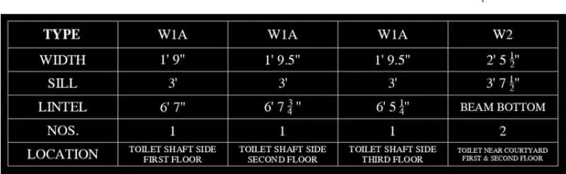
RESULT:
The window schedule is created as shown in the figure.
DRAWING 3
AIM:
To create the drawing template as shown in the figure
INTRODUCTION:
Creating a table that contains drawing details
PROCEDURE:
1.In command box type line and create a tabular column as given
2.Now type ST>romans.shx>8" (height) >left
3.Type text command to insert text in required boxes
4.now type MTEXT (multiline text) > symbols > to get diameter symbol
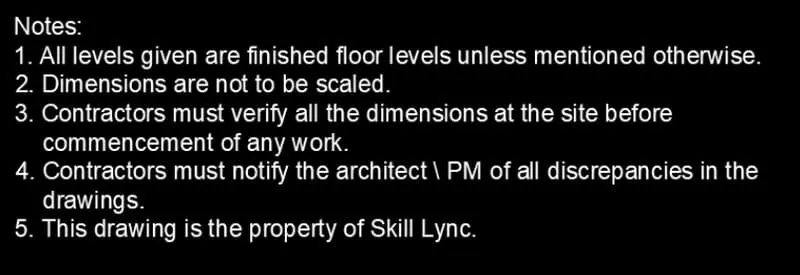

RESULT:
The drawing template is created as shown in the figure.
DRAWING 4
AIM:
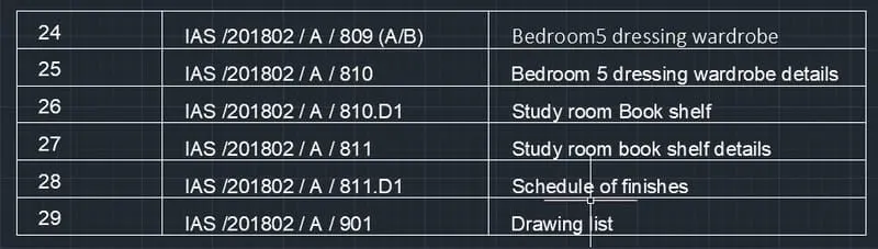
To create the list of drawing as shown in figure
INTRODUCTION:
The table contains a various list of drawing details
PROCEDURE:
1.Create a new table style of required text style, text height, etc
2.Enter the number of rows and columns, set cell type, and insert in the table
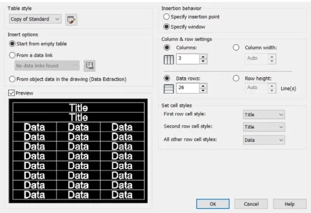
Enter the data
Adjust the cell type and list down as required
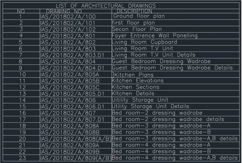
RESULT:
The list of drawings is created as shown in figure.
DRAWING 5
AIM:
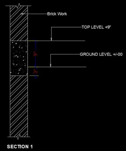
To create beam details as shown in figure
INTRODUCTION:
Creating a beam and brickwork and sizes are shown
PROCEDURE:
1.Make 2 parallel lines 45" long at a distance of 6" from each other
2.Using breaking line command, make breaking line at top and bottom
3.Draw a horizontal line as shown in figure
4.Give required labeling
5.Modify the dimension to match the question
6.Give hatch work of brick as shown in figure.
RESULT
The beam details are created as shown in figure.