Creating a Floor plan, Footing detail and Isometric view using AutoCad
AIM:
To create a Floor plan, Footing detail and Isometric view using AutoCad.
INTRODUCTION:
This assignment's main objective is to get in touch with various tools in AutoCAD like rectangle,polyline,modifications tools like copy,move, different modes like snap and grid,different settings like draftting setting and ortho mode.These tools,modes,settings can be better understood by this assignment.
PART 1:CROSSSECTION OF LOAD BEARING WALL OVER SPREAD FOOTING.
PROCEDURE:
Step:1 -
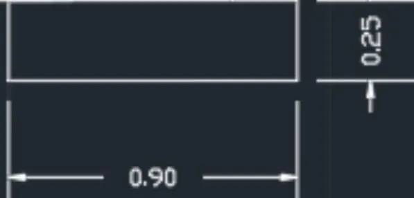
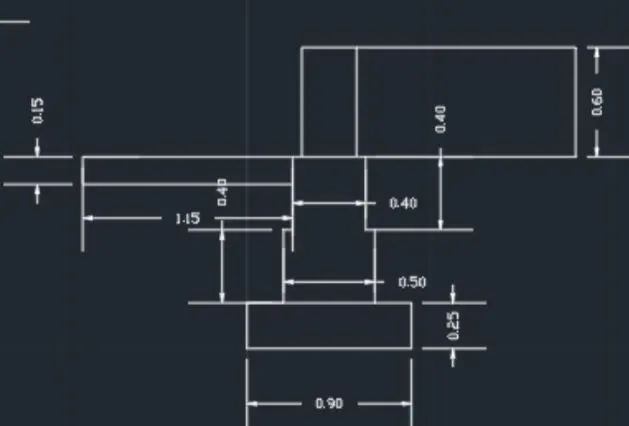
Create rectangle by typing "REC" in command box
1.Specify the first corner point as (5,5)
2.specify the length of the rectangle =0.9 units in the command box
3.specify width of rectangle = 0.25 units in command box.
Step:2-
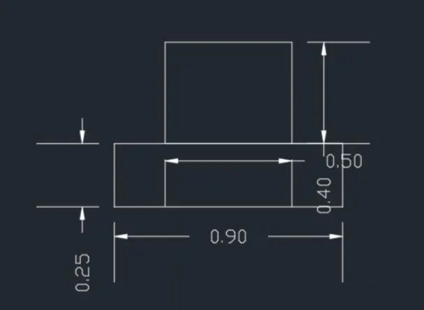
Create another rectangle -"REC" in command box.
1.Specify the first corner point which is 0.2 units from the starting point of first rectangle.
2.Enter the length of rectangle as 0.5 units the width of rectangle as 0.4 units.
Step:3 -
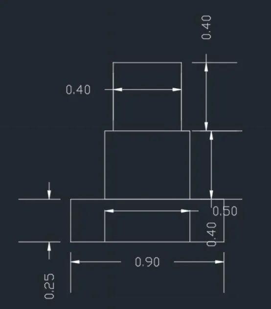
Create the third rectangle command- "REC"
1.Specify the first corner point which is 0.05 units from the starting point of second rectangle.
2.Enter the length of rectangle as 0.4 units and the width of rectangle as 0.4 units.
Step :4 -
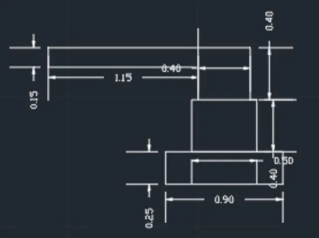
Line is drawn from the corner of third rectangle, command "L"
1.Give the length as 1.15 units
2.Move cursor downwards and give value 0.15 units and right and give length as 1.15 units.
Step:5 -
Fourth rectangle is drawn command -"REC"
1.Specify the first corner point at a distance of 0.05 from the third rectangle.
2.Give the length as 0.3 and width as 0.6
Step:6 -
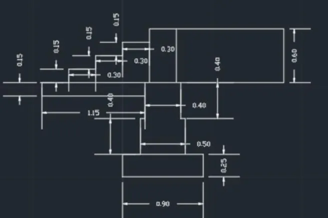
1.from the line drawn in step 4, at a distance of 0.3, draw another line with the distance of 0.15 units vertically and 0.3 units horizontally.
2.Continue it two more times, until 3 steps are created.
Step 7 -
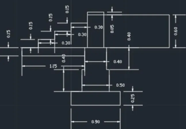
Draw another rectangle above fourth rectangle using command "REC"
1.Specify the corner point as the corner of the fourth rectangle
2.Click on dimensions - give length as 0.3 units and width as 0.5 units.
Step 8 -
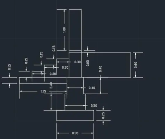
Draw the fifth rectangle using command "REC"
1.specify the corner point as the corner of fourth rectangle
2.click on dimension give length as 0.3 units and width as 1 unit
3.Erase the unwanted line using command "TRIM"
RESULT:
The cross section of load bearing wall over spread footing is drawn.
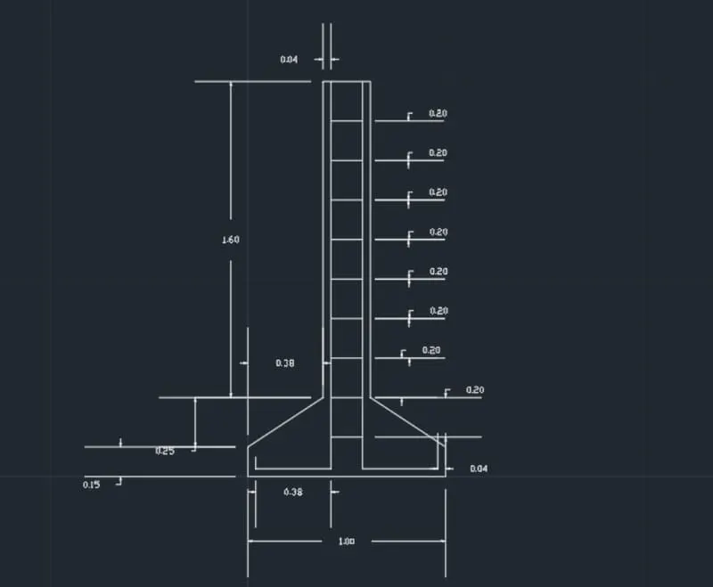
CROSS SECTION OF AN ISOLATED FOOTING :
AIM:
To draw cross section of an isolated footing .
INTRODUCTION:
The cross-section of the isolated footing using AutoCAD is created by lines and rectangle command. The procedure is written and results are written after creating the cross-section of the isolated footing using AutoCAD.
Commands used:
- LINE
- OFFSET
- TRIM
PROCEDURE:
1.Draw a line of 1 unit
2.Specify the line using coordinates @0,0.15 units
3.Give next coordinate as @0.38,0.25
4.Give next coordinate as @0,1.6
5.Now use the mirror command and copy the drawing
6.Join the required lines
7.Using the offset command draws a line of 0.04 units from the left line
8.Do the same for Right, left, bottom and end
9.Trim the unwanted lines
10.Using the offset command draws a line of 0.2 units from the top line and draw 9 lines as such
11.Trim the excess lines
12.Click dimension and show dimensions for the structure.
RESULT:
The cross section of isolated footing using AutoCAD is created.
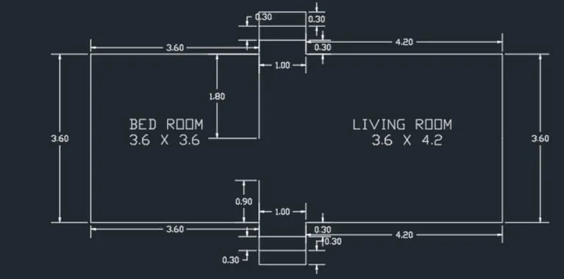
LINE DIAGRAM OF TWO BEDROOM BUILDING
AIM
To draw a line diagram of two bedroom building.
INTRODUCTION
The line diagram of 2 bedroom building using AutoCAD is created by lines and rectangle command. The procedure is written and results are written after creating the line diagram of 2 bedroom building using AutoCAD.
COMMANDS USED
1.Line (CTRL+L)
2.Rectangle (ctrl + rec)
3.Offset (O + enter + select line + Enter measurement + enter)
4.Trim (Tr+double enter)
PROCEDURE
1.Draw a rectangle of length and width (8.2,3.6)
2.Explode the rectangle using explode command
3.Using the offset command draws a line on the left and right side of distance 3.6 units
4.Draw an offset line of 0.3 units two lines bottom
5.Repeat the step two times
6.Trim unwanted lines
7.Now draw a line from the left bottom end to upwards of 0.9 units
8.Now draw a line from the left top end to downwards of 1.8 units
9.Check well and trim unwanted lines
10.Click dimension and show dimensions for the structure.
RESULT:
A line diagram of two bedroom building has been created using AutoCAD.
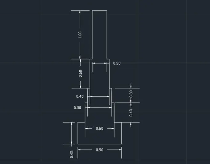
CROSS-SECTIONS OF LOAD-BEARING WALLS SHOWING FOUNDATION DETAILS
AIM
To create a cross-section of the load-bearing wall showing foundation using AutoCAD.
INTRODUCTION
The cross-section of the load-bearing wall showing foundation using AutoCAD is created by lines and rectangle command. The procedure and result are written after creating the cross-section of the loadbearing wall showing foundation using AutoCAD.
Commands Used
1.Line (CTRL+L)
2.Rectangle (CTRL+REC)
3.Trim (Tr+double enter)
PROCEDURE
1.Create a rectangle by typing the REC command
2.Specify first corner point as (5,5)
3.Specify the length and width of the rectangle (0.9,0.45)units
4.Now create another rectangle using the starting point of the first rectangle which is 0.15 units from the corner
5.Specify the length and width of the rectangle (0.6,0.4)units
6.Now create another rectangle using the starting point of the second rectangle which is 0.05 units from the corner
7.Specify the length and width of the rectangle (0.5,0.3)units
8.Now create another rectangle using the starting point of the third rectangle which is 0.05 units from the corner
9.Specify the length and width of the rectangle (0.4,0.6)units
10.Now create another rectangle using the starting point of the fourth rectangle and enter length and breadth as ( 0.3,1) units
11.Erase unwanted line using trim command
12.Click dimension and show dimensions for the structure
RESULT:
The cross section of load bearing wall showing foundation is created using AutoCAD.
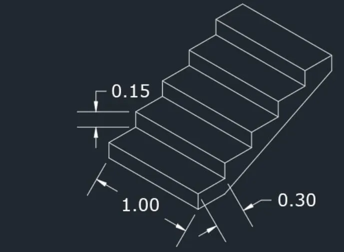
ISOMETRIC VIEW OF STAIRCASE
AIM
To draw the Isometric view of the staircase
INTRODUCTION
The Isometric view of the staircase using AutoCAD is created by lines and rectangle command. The procedure and result are written after creating the Isometric view of the staircase using AutoCAD.
Commands Used
1.Line (CTRL+L)
2.Isometric plane
3.Trim (Tr+double enter)
PROCEDURE
1.Put snap off, Grid off, and Isometric snap ON
2.Ortho On
3.Draw a line of 1 unit in -X-direction
4.Draw a line of 0.15 units in +Y-direction
5.Draw a line of 1 unit in X-direction
6.Draw a line of 0.15 units in -Y-direction
7.From the last drawn point draw a line of 0.3 units at the back
8.draw a line 1 unit at the right
9.draw a line 0.3 unit at the front
10.Copy the diagram and repeat it 4 times
11.With iso-plane, right join two lines
12.Erase unwanted line using trim command
13.Click dimension and show dimensions for the structure
RESULT:
The steps are drawn in isometric view using AutoCAD.
ISOMETRIC VIEW OF GABLE WALL
AIM
To draw the Isometric view of the Gable wall
INTRODUCTION
The Isometric view of the Gable wall using AutoCAD is created by lines and rectangle command. The procedure and result are written after creating the Isometric view of the Gable wall using AutoCAD.
Commands Used
1.Line (CTRL+L)
2.Isometric plane
3.Trim (Tr+double enter)
PROCEDURE
1.Put snap off, Grid off, and Isometric snap ON
2.Ortho On
3.Draw a line of 1 unit in -X-direction
4.Draw a line of 3 units in +Y-direction
5.Draw a line of 0.3 units in -X-direction
6.Draw a line of 3 unit in -Y-direction
7.Draw a line of 0.3 units in X-direction
8.Draw a line of 1 unit in right and 2.42 in downwards
9.Draw a line of 0.3 units on the left side which intersects the top line
10.Draw a line of 1 unit on the right side and 3 units upwards
11.Draw a line at the bottom left corner @1.5 units and extend the line of 4 units upwards
12.Join the required lines
13.Draw the vertical line @0.3 and join the required lines
14.Erase unwanted line using trim command
15.Click dimension and show dimensions for the structure
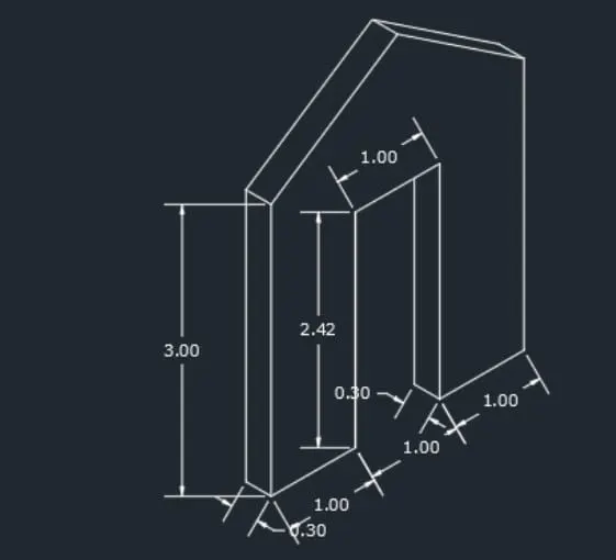
RESULT:
The isometric view of the gable wal is created using AutoCAD.