Creation of Column Schedule and Drawing Template using AutoCad
11/06/21
Answers
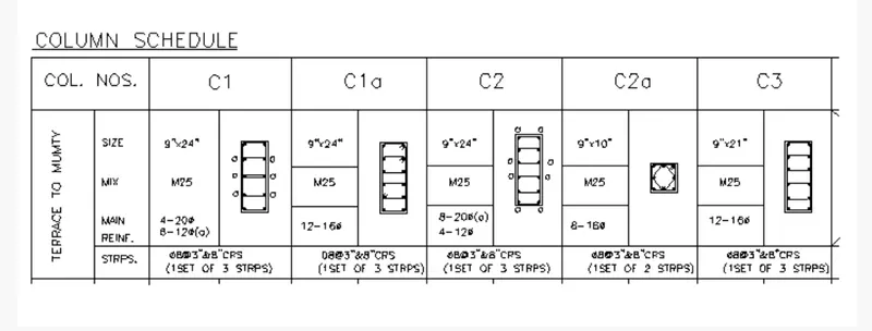
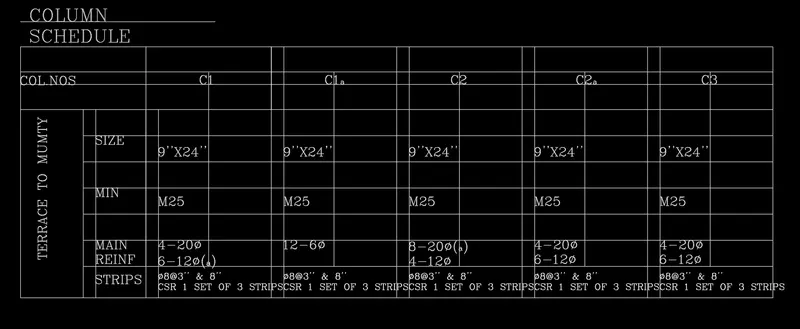
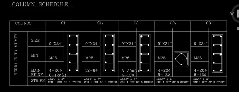
1. Create a column schedule as shown in the figure.
Aim
To Create a column schedule using AutoCAD
Procedure
Step-1 opening to the AutoCAD software and entering the workspace.
Step-2 Setting limits >specify lower-left corner:0,0
Step-3 specify upper-left corner:100,100
Step-4 Set>units>Architectural>intersectional scale>inches
Step-5 Limmax>100,100
Step-6 rectangle command> to create a rectangle of required dimension
Step-7 line command> to draw the line as the reference.
Step-8 offset command> offset the x-axis in the required dimension and repeat the same in the Y-axis
Step-9 trim command> trim all unnecessary lines remaining.
Step-10 multitext command>make the text in the required size and define location.
Step-11 rotate command>rotate the text towards the Y-axis
Step-12 copy command>copy the text to all required areas.
Step-13 rectangle command> to create the rectangle and place the circle on all side of the rectangle
Step-14 line command> the line help to join the circles presents in the column rebars
Step-15 close the entire object
Step-16 and save the file for feature use.
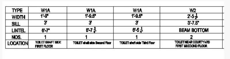
2. Create a window schedule as shown in the figures:
Aim
To Create a window schedule using AutoCAD
Procedure
Step-1 opening to the AutoCAD software and entering the workspace.
Step-2 Setting limits >specify lower-left corner:0,0
Step-3 specify upper-left corner:100,100
Step-4 Set>units>Architectural>intersectional scale>inches
Step-5 Limmax>100,100
Step-6 rectangle command> to create a rectangle of required dimension
Step-7 line command> to draw the line as the reference.
Step-8 offset command> offset the x-axis in the required dimension and repeat the same in the Y-axis
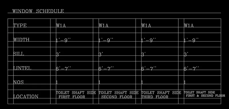
Step-9 trim command> trim all unnecessary lines remaining.
Step-10 multitext command>make the text in the required size and define location.
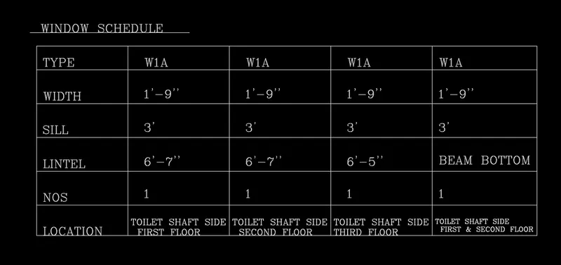
Step-11 close the entire object
Step-12 and save the file for feature use.
3. Create the drawing template as shown in the figure:
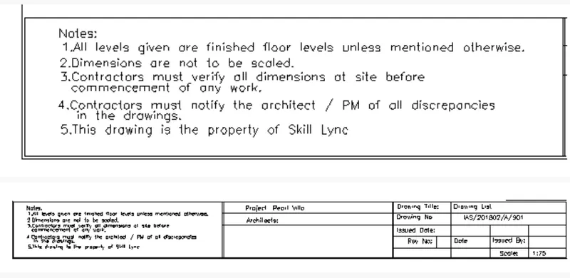
Aim
Create the drawing template using AutoCAD
Procedure
Step-1 opening to the AutoCAD software and entering the workspace.
Step-2 Setting limits >specify lower-left corner:0,0
Step-3 specify upper-left corner:100,100
Step-4 Set>units>Architectural>intersectional scale>inches
Step-5 Limmax>100,100
Step-6 rectangle command> to create a rectangle of required dimension
Step-7 line command> to draw the line as the reference.
Step-8 offset command> offset the x-axis in the required dimension and repeat the same in the Y-axis
Step-9 trim command> trim all unnecessary lines remaining.
Step-10 multitext command>make the text in the required size and define location.
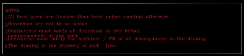
Step-11 separately makes the notes part after making it join together.
Step-12 copy command>copy the text to all required areas.
Step-14 line command> the line help to join small boxes
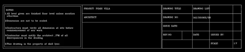
Step-15 close the entire object
Step-16 and save the file for feature use.
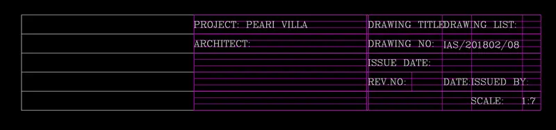
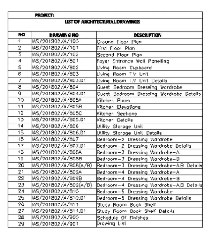
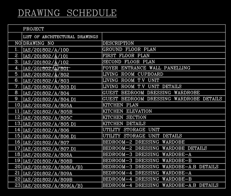
4. Create the list of drawing schedule as shown in the figure:
Aim
To Create the list of drawing schedule using AutoCAD
Procedure
Step-1 opening to the AutoCAD software and entering the workspace.
Step-2 Setting limits >specify lower-left corner:0,0
Step-3 specify upper-left corner:100,100
Step-4 Set>units>Architectural>intersectional scale>inches
Step-5 Limmax>100,100
Step-6 rectangle command> to create a rectangle of required dimension
Step-7 line command> to draw the line as the reference.
Step-8 offset command> offset the x-axis in the required dimension and repeat the same in the Y-axis.
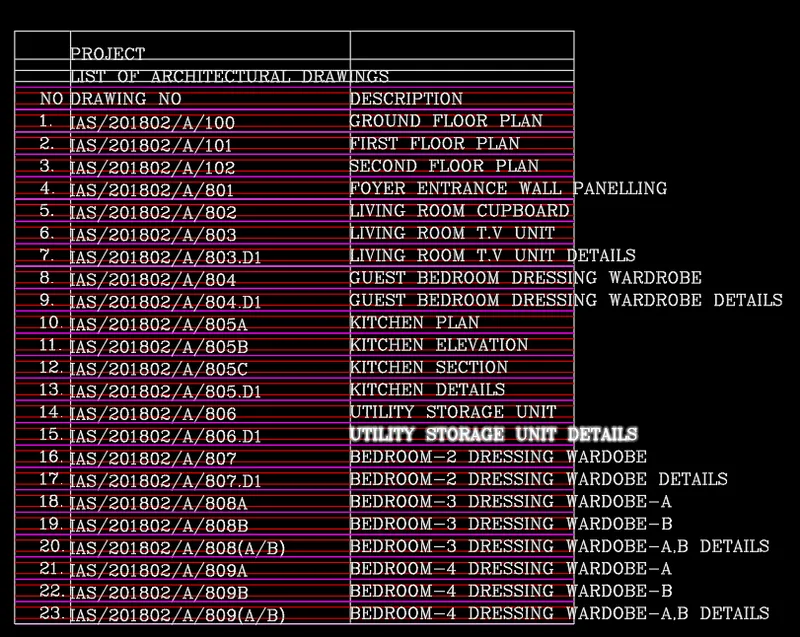
Step-9 trim command> trim all unnecessary lines remaining.
Step-10 multitext command>make the text in the required size and define location.
Step-11 rotate command>rotate the text towards the Y-axis
Step-12 copy command>copy the text to all required areas.
Step-13 rectangle command> to create the rectangle and place the circle on all side of the rectangle
Step-14 close the entire object
Step-15 and save the file for feature use.
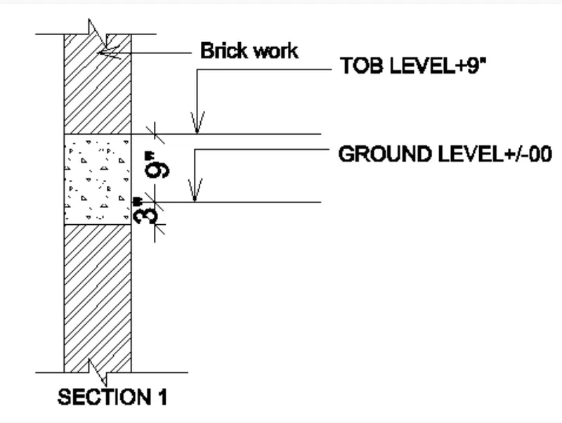
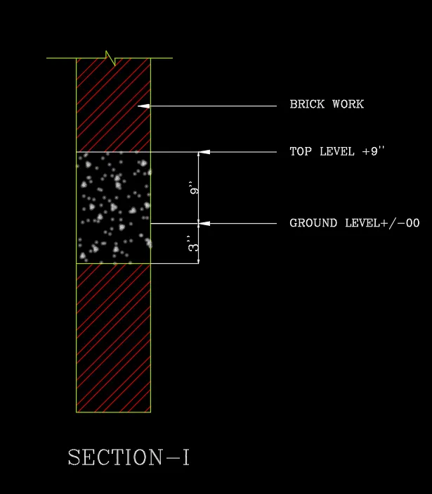
5. Create the Beam detail as shown in the figure and provide text wherever given.
Aim
To Create the Beam detail and provide the text using the AutoCAD
Procedure
Step-1 opening to the AutoCAD software and entering the workspace.
Step-2 Setting limits >specify lower-left corner:0,0
Step-3 specify upper-left corner:100,100
Step-4 Set>units>Architectural>intersectional scale>inches
Step-5 Limmax>100,100
Step-6 rectangle command> to create a rectangle of required dimension
Step-7 line command> to draw the line as the reference.
Step-8 offset command> offset the x-axis in the required dimension and repeat the same in the Y-axis
Step-9 trim command> trim all unnecessary lines remaining.
Step-10 multitext command>make the text in the required size and define location.
Step-11 leader command> to make the arrows
Step-12 multitext command>make the text in the required size and define location.
Step-13 and make the top level, ground level, brick area make notify.
Step-14 hatch command> helps as to pick the area and made a required hatchs
Step-15 close the entire object
Step-16 and save the file for feature use.