Creation of Column Schedule and Drawing Template using AutoCad
Q1
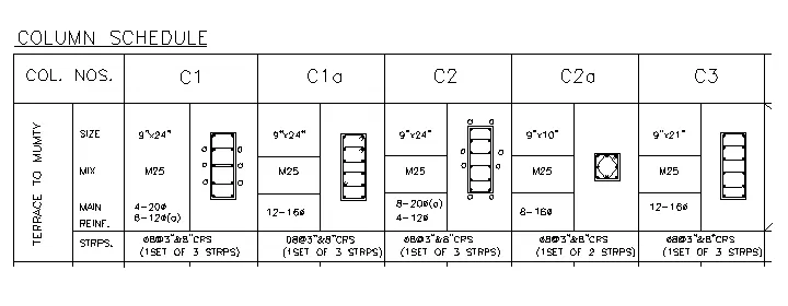
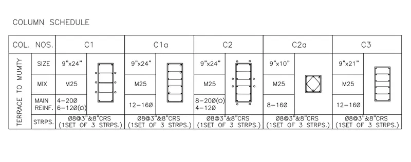
Create a column schedule as shown in the figure.
Note: Create a column schedule with the help of lines. Also, insert text with the help of Dtext command or Single Line text.
Hint: Use font name: romans.shx; Height: 8”, Justify: Left
AIM
Create a column schedule as shown in the above figure.
INTRODUCTION
The column schedule is a schedule which the details of column will be collected in the construction for design purpose.
PROCEDURE
Open the AutoCAD Application and create a new AutoCAD file with imperial settings. Set the units in 'Engineering' and precision (0'-0.0"), limits by typing 'LIMMAX in command line (100',100') and zoom all by typing 'Z' in command line (Zoom All). Adjust font name as romans.shx; Height as 8” in the 'TEXTSTYLE' settings.
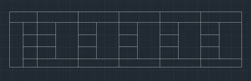
1. Draw the colum schedule table
- Using 'LINE', 'RECTANG', 'COPY' and 'MOVE', the table for column schedule is created
2. Provide annotations given in the figure
- Using 'TEXT' tool, type all the labels given in the figure
- Using 'SCALE', 'MOVE', and 'COPY' tool, place the text in the appropriate box as shown
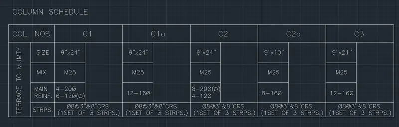
3. Draw the columns
C1:
- Using 'RECTANG' tool, draw a rectangle of 9"x24"
- Using 'OFFSET' tool, offset cover distance 0.5"
- Using 'CIRCLE' tool, draw a circle of dia 20mm and 12mm
- Using 'PLINE' tool, draw a shape as shown in the figure
- Using 'COPY', 'ARRAY', 'MOVE' tool, place the circle and shapes according to the given drawing
- Using 'LINE' tool, draw the stirrups shown in figure
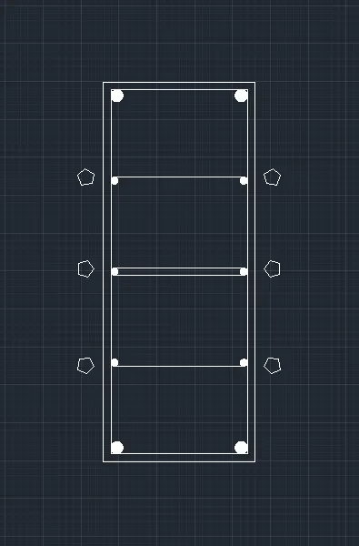
C1a:
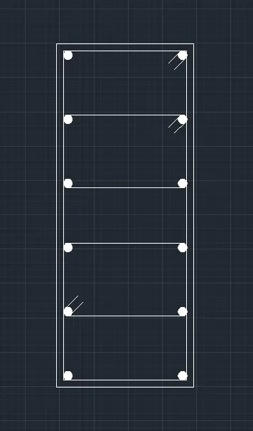
- Using 'RECTANG' tool, draw a rectangle of 9"x24"
- Using 'OFFSET' tool, offset cover distance 0.5"
- Using 'CIRCLE' tool, draw a circle of dia 16mm
- Using 'COPY' tool, 'ARRAY', 'MOVE', place the circle according to the given drawing
- Using 'LINE' tool, draw the stirrups and ties shown in figure
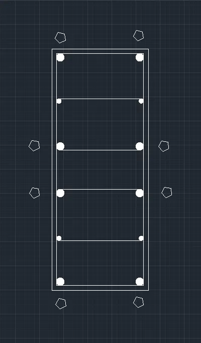
C2:
- Using 'RECTANG' tool, draw a rectangle of 9"x24"
- Using 'OFFSET' tool, offset cover distance 0.5"
- Using 'CIRCLE' tool, draw a circle of dia 20mm and 12mm
- Using 'PLINE' tool, draw a shape as shown in the figure
- Using 'COPY' tool, 'ARRAY', 'MOVE', place the circle and shapes according to the given drawing
- Using 'LINE' tool, draw the stirrups and ties shown in figure
C2a:
- Using 'RECTANG' tool, draw a rectangle of 9"x10"
- Using 'OFFSET' tool, offset cover distance 0.5"
- Using 'CIRCLE' tool, draw a circle of dia 16mm
- Using 'COPY' tool, 'ARRAY', 'MOVE', place the circle according to the given drawing
- Using 'LINE' tool, draw the stirrups and ties shown in figure
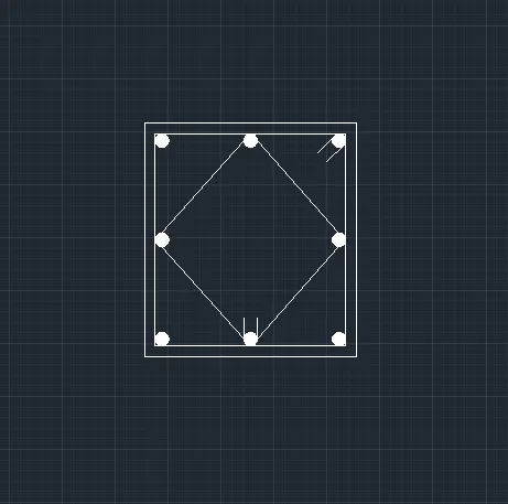
C1a:
- Using 'RECTANG' tool, draw a rectangle of 9"x21"
- Using 'OFFSET' tool, offset cover distance 0.5"
- Using 'CIRCLE' tool, draw a circle of dia 16mm
- Using 'COPY' tool, 'ARRAY', 'MOVE', place the circle according to the given drawing
- Using 'LINE' tool, draw the stirrups shown in figure
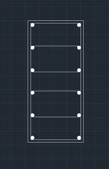
4. Place the columns inside the assigned box as per the figure
- Using 'MOVE' tool, place all the columns in their respective boxes
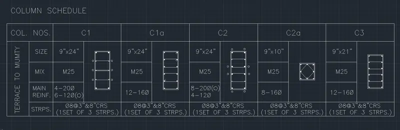
RESULT
A column schedule is created as per the given figure
Q2
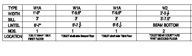
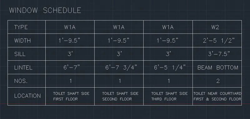
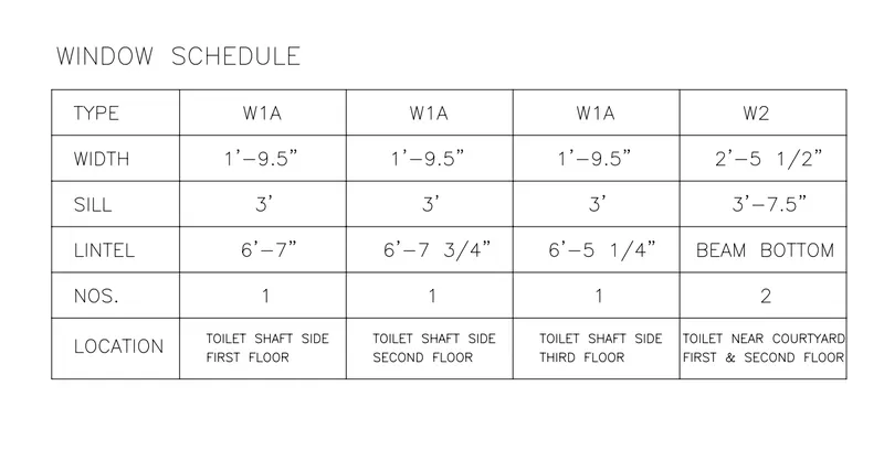
Create a window schedule as shown in the figures:
Window Schedule:
AIM
Create a window schedule as shown in the figure
INTRODUCTION
The window schedule is a schedule in which the details of all windows will be collected in the construction for design purpose.
PROCEDURE
Open the AutoCAD Application and create a new AutoCAD file with imperial settings. Set the units in 'Engineering' and precision (0'-0.0"), limits by typing 'LIMMAX in command line (100',100') and zoom all by typing 'Z' in command line (Zoom All). Adjust font name as romans.shx; Height as 8” in the 'TEXTSTYLE' settings.
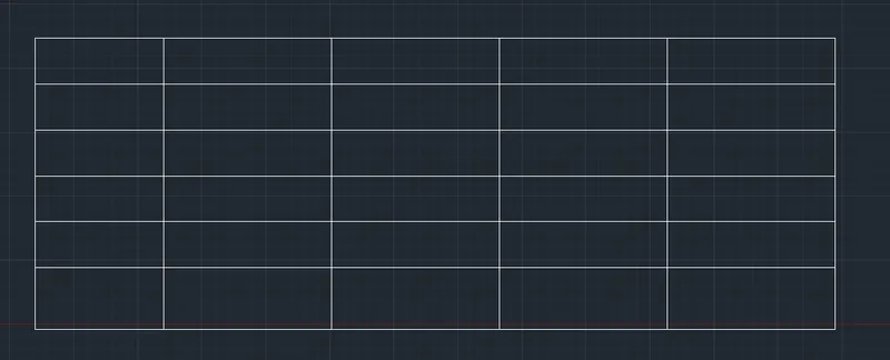
1. Draw the table
- Using 'LINE', 'OFFSET', 'TRIM', 'ERASE', create a table for the window schedule
2. Provide annotations given in the figure
- Using 'TEXT' tool, type all the labels given in the figure
- Using 'SCALE', 'MOVE', and 'COPY' tool, place the text in the appropriate box as shown
RESULT
The window schedule is created as per the given figure
Q3
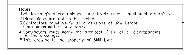
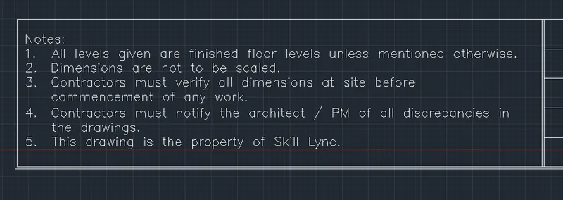
Create the drawing template as shown in the figure:< Use the Notes as in the figure>

AIM
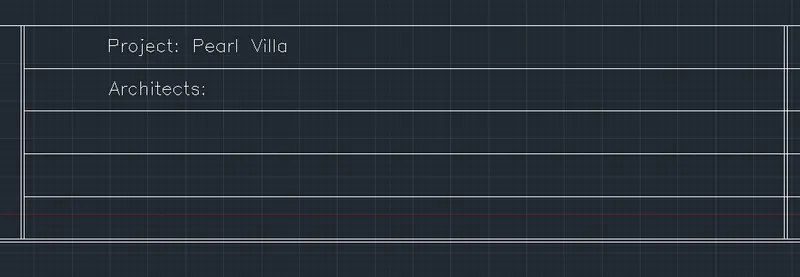
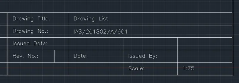
Create the drawing template as shown in the figure
INTRODUCTION
A drawing template in AutoCAD is a form used as a guide to making something.
PROCEDURE
Open the AutoCAD Application and create a new AutoCAD file with imperial settings. Set the units in 'Engineering' and precision (0'-0.0"), limits by typing 'LIMMAX in command line (100',100') and zoom all by typing 'Z' in command line (Zoom All). Adjust font name as romans.shx; Height as 8” in the 'TEXTSTYLE' settings.
1. Draw the table
- Using 'LINE', 'OFFSET', 'TRIM', 'ERASE', 'DIVIDE' tool, create a table for the drawing template

2. Provide annotations given in the figure
- Using 'MTEXT' tool, type all the labels given in the figure
- Using 'MOVE', and 'COPY' tool, place the text in the appropriate box as shown

RESULT
The drawing template is created as per the given figure.

Q4
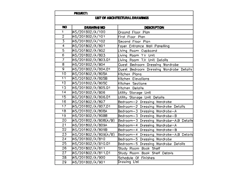
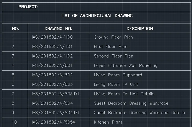
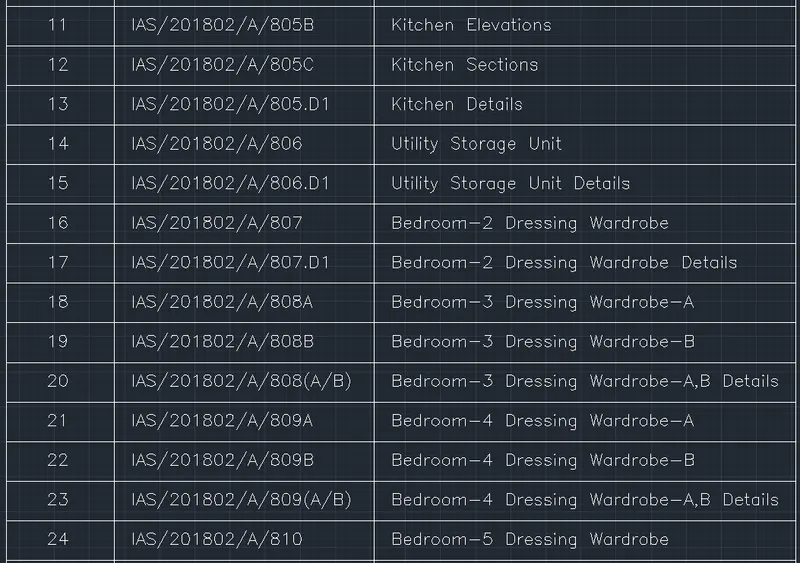
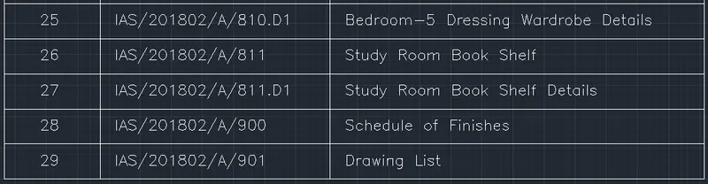
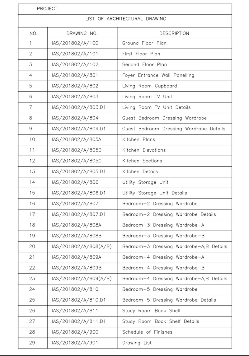
Create the list of drawing schedule as shown in the figure:
AIM
To create the list of drawing schedule as shown in the figure.
INTRODUCTION
A schedule of drawings is an itemised list of drawings required for a building project.
PROCEDURE
Open the AutoCAD Application and create a new AutoCAD file with imperial settings. Set the units in 'Engineering' and precision (0'-0.0"), limits by typing 'LIMMAX in command line (100',100') and zoom all by typing 'Z' in command line (Zoom All). Adjust font name as romans.shx; Height as 8” in the 'TEXTSTYLE' settings.
1. Draw the table
- Using 'LINE', 'OFFSET', 'TRIM', 'ERASE', 'DIVIDE' tool, create a table for the drawing template

2. Provide annotations given in the figure
- Using 'MTEXT' tool, type all the labels given in the figure
- Using 'MOVE', and 'COPY' tool, place the text in the appropriate box as shown
RESULT
The list of drawing schedule is created as per the given drawing.
Q5
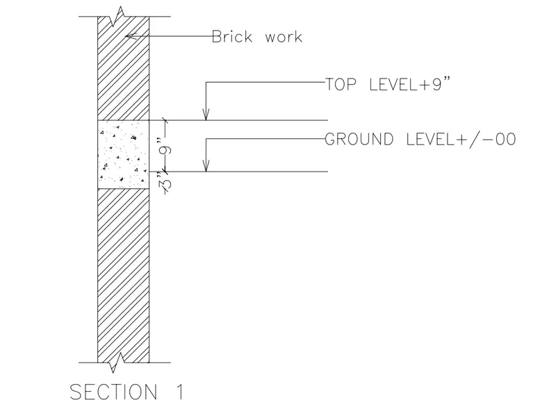
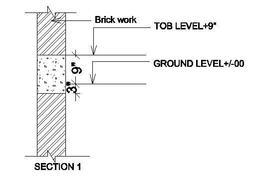
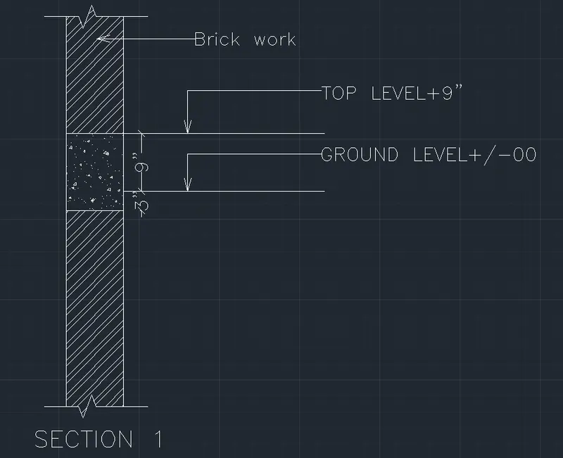
Create the Beam detail as shown in the figure and provide text wherever given.
AIM
To create the beam detail as shown in the figure
INTRODUCTION
A beam is a structural element that primarily resists loads applied laterally to the beam's axis. The details of the beam is shown in the beam detail.
PROCEDURE
Open the AutoCAD Application and create a new AutoCAD file with imperial settings. Set the units in 'Engineering' and precision (0'-0"), limits by typing 'LIMMAX in command line (100',100') and zoom all by typing 'Z' in command line (Zoom All).
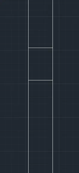
1. Draw the brick work
- Using 'LINE', 'OFFSET' tools, draw the brick work as shown in the figure
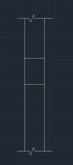
2. Draw break line
- Using 'BREAKLINE' tool, draw break lines on both sides
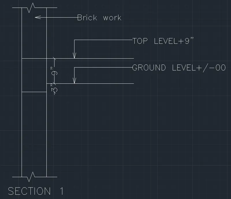
3. Provide annotations given in the figure
- Using 'MTEXT', 'MLEADER' tool, type all the labels given in the figure
- Using 'MOVE', and 'COPY' tool, place the text in the appropriate area as shown
4. Using 'HATCH' tool, hatch according to the figure
RESULT
The beam detail is sketched according to the given figure.