Creation of Column Schedule and Drawing Template using AutoCad
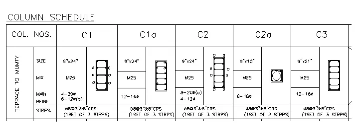
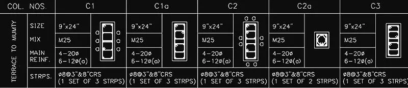
AIM: To create a column schedule as shown in the figure.
Introduction
1. Column C1 is provided with 4 bars of 20 mm dia and 6 bars of 12mm dia and marking them with a
2. Column C1a and columnC3 are provided with 12 bars of 16mm dia bars
3.Column C2 is provided with 8 bars of 20mm dia and 4 bars of 12mm dia marked with a
4. Column C2a is provided with 8 bars of 16mm dia.
5. Al colums are provided with 8mm dia stirrups with 3" spacing cc near the ends and 8" cc in mid length
6. The cc for all columns is assumed to be 1.5" as per IS 256
Procedure
1. Create a new file in AutoCAD.
2. Convert the dias of the bars into inches by dividing them by 25.4
20- 0.7874
16- 0.6299
12- 0.4725
8- 0.3150
The dimensions for the bars on the left are the same as that of the bars on the right . The longitudinal and stirrups are hatched with a white solid fill.
3. Draw a column as shown in the above figure
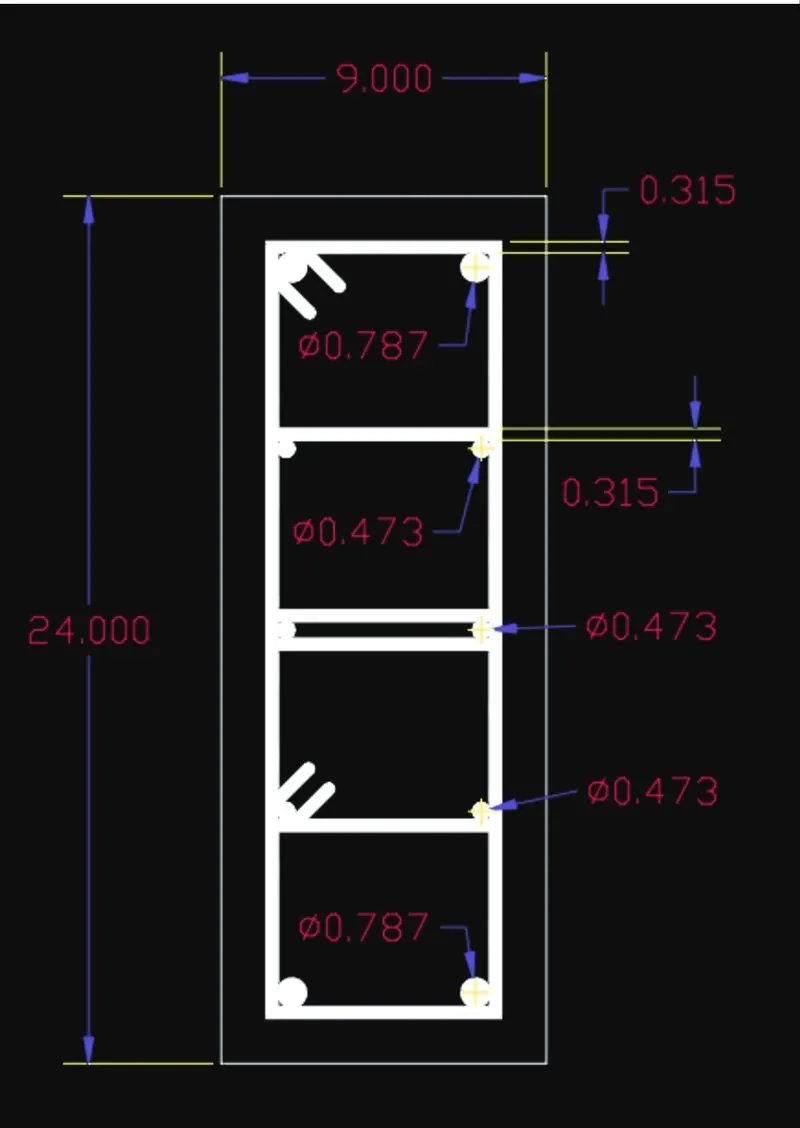
4. Make the column C1a as shown
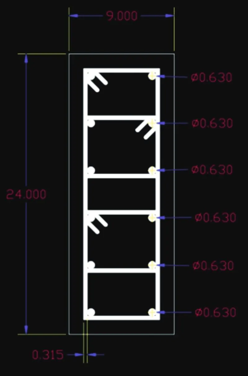
5. Make the column C2 as shown
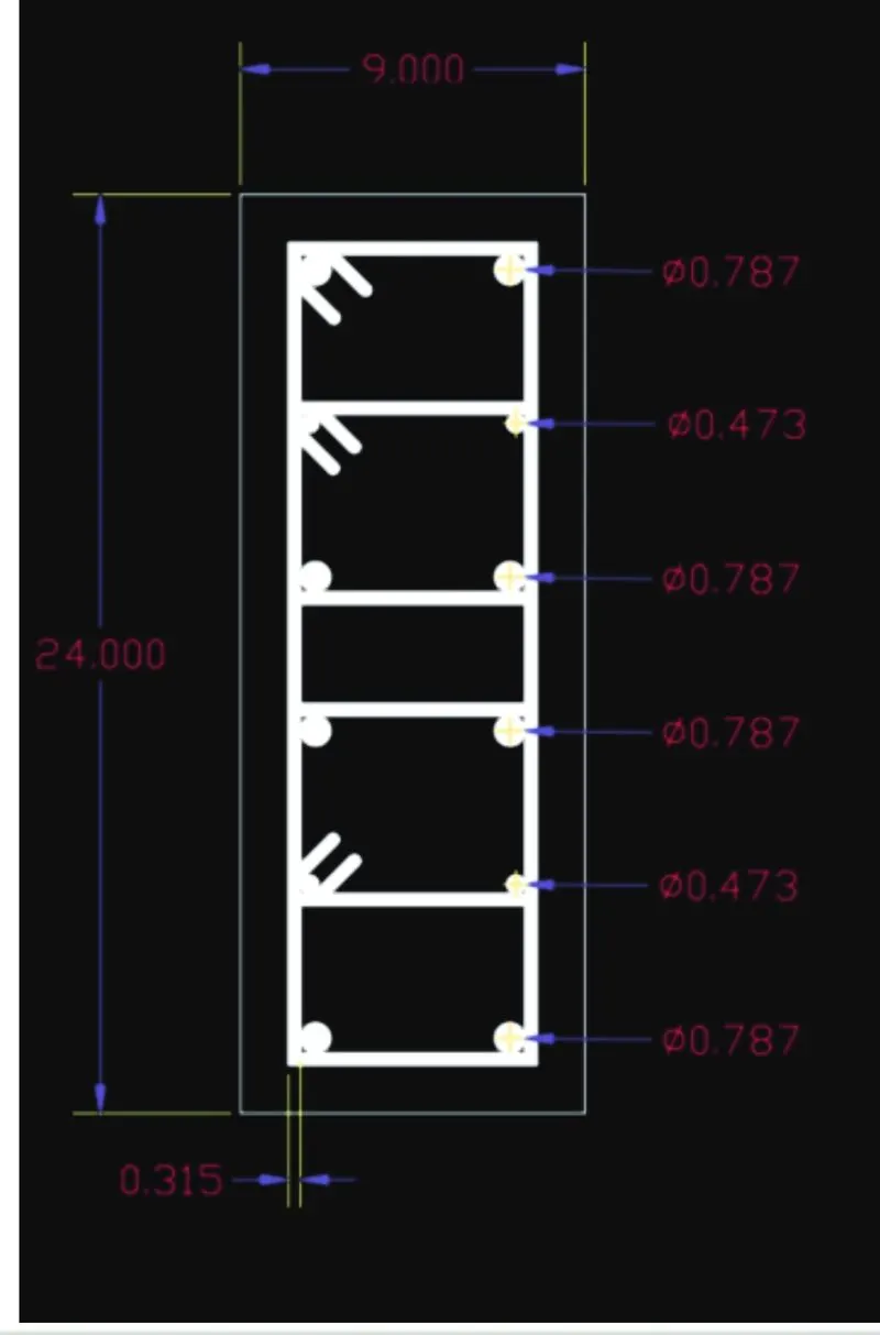
6. Make column C2a as shown
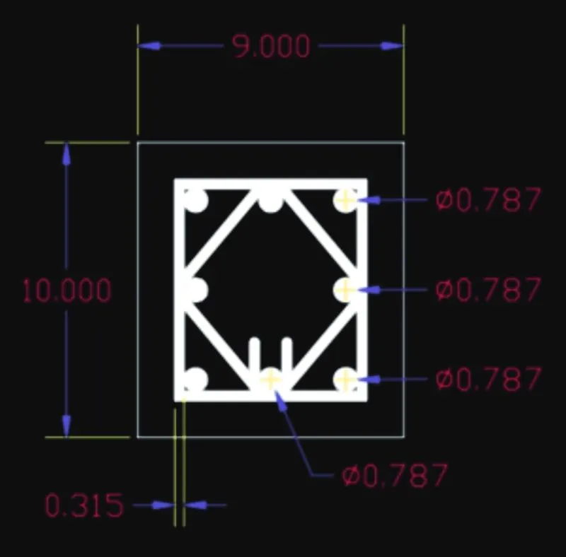
7. Make the column C3 as shown
8. Make a table as shown
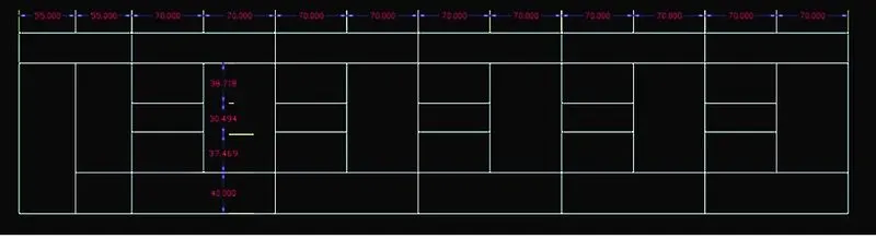
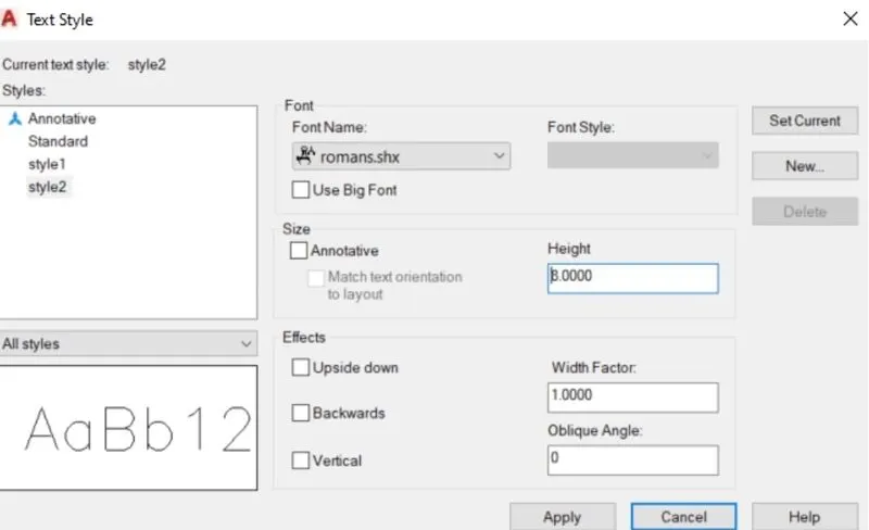
9. Make a new text style with the font-romans.shx and height 8"
10. Table is as above
11. Scale the columns made in steps 3-7 as per the adjustment in table
2. Create a window schedule as shown in the figures:
Introduction
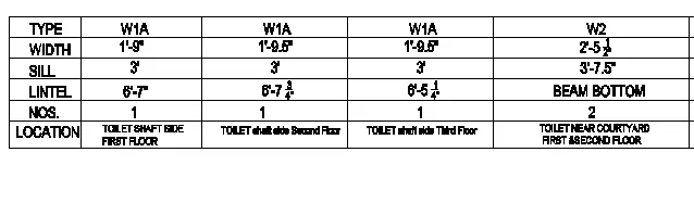
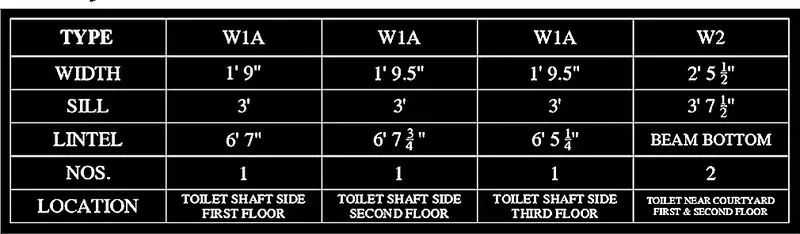
The table contains the width,sill and lintel height,number and respective location for different types of beams
Procedure
1.Make the following table
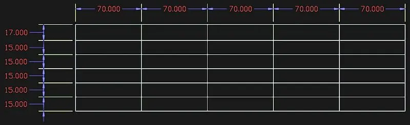
2.Using multiline fill the data with justification middle center MC
Result
3. Create the drawing template as shown in the figure

Procedure:
1.Make the following table.
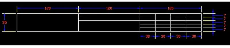
2. Using multitext with height 2.5" and font Ariel
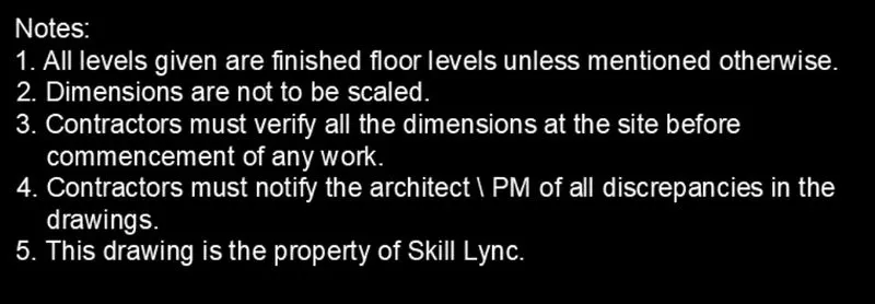
3. Type the rest of the info in respective boxes with same annotations
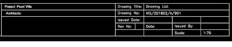
Result

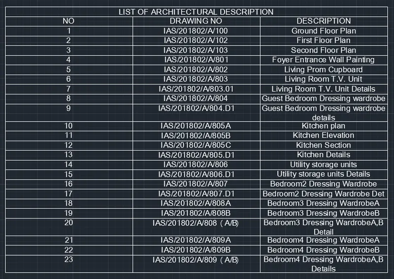
4. Create the list of drawing schedule as shown in the figure:
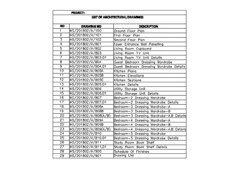
Procedure:
1. Open the table command
2. Create a table by selecting the required text style,text height etc
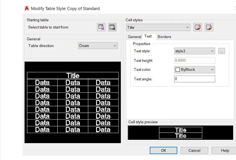
3. Insert the no of rows and colums as per needed
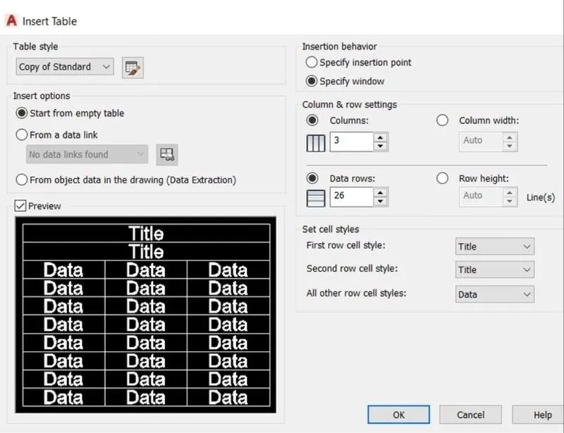
4. Adjust the size of rows and columns
5.Enter the data
Result:
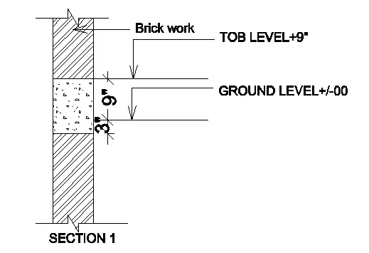
5. Create the Beam detail as shown in the figure and provide text wherever given.
Procedure:
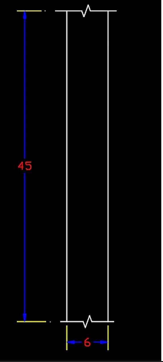
1. Make two parallel lines 45" long ang 6" wide
2.Using the breakline command apply to top and bottom
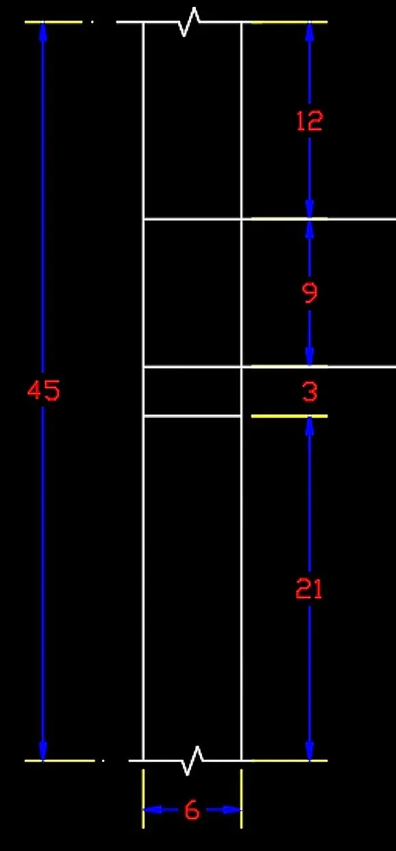
3.Give required labelling using multitext
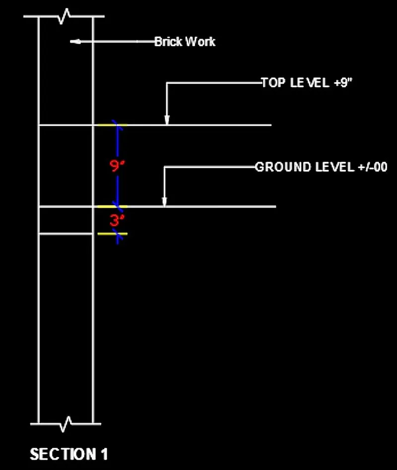
4. Modify the dimensions to match the info in the question
5.Give the hatching command as per requiremet
Result