Creation of Column Schedule and Drawing Template using AutoCad
Aim: Create a column schedule
Introduction: Create a column schedule by using AutoCad
Procedure:
Step1:
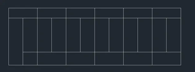
- To create a table
- Draw a rectangle by typing “REC” in command box
- Make a rectangle of 60’x 20’
- Next take the offset command
- Make the 6 columns with the offset of 10’ to each
- Make the 6 columns with the offset of 5’ to each
- Make the 3’,6” offset from the top line and 4’,6”
- Next take the command trim by typing “TR” in the command box
- Now trim the extra and unwanted lines
Step2:
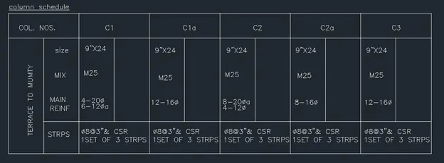
- Entering the text
- Now take the command “TEXT”
- Take the height of the text as 8” and angle of the text as 0 all
- Now make the heading as column schedule
- Now copy the heading by the command “CO”
- Next rotate it by rotate command “RO” at an angle of 90 and edit the heading as “TERRCE TO MUMTY”.
- Now to change the text style take the command “ST” select the font name as “romans.shx”
- Then copy the text create and edit the required text .
Step3:
Drawing of column section c1:
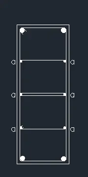
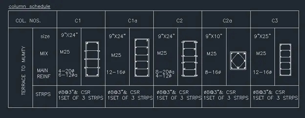
- Column of 9”x24” having 20mm dia of reinforcement bar at 4 corners and 12mm dia of 6 reinforcement bar at middle connected by 8mm dia strip
- Draw a rectangle of 9”x24” by using command “REC”
- Now take the offset command and make an offset of 40mm or 0.5”
Drawing of reinforcement:
- Take the circle tangent, tangent, radius mark the point of tangent at top and side line of column and make a circle of radius 10mm
- Next take the mirror command give the mirror line then place the bar at bottom and other side of the column
- Take the fillet command give the radius 2” for all the 4 sides
- Now take the command “div” and give the segment value 5
- Next take the circle command and make bar of 12mm dia and place at marked point
- Take the mirror command and mirror it in other side
- Now take the hatch command and take the solid hatch and hatch all the reinforcement bars
Drawing of strips:
- Take the line mark the line from a right to left bar top and bottom
- To make the hooks mark the line right and left side of the bar and trim it now place it at by rotating at required angle
Step4:
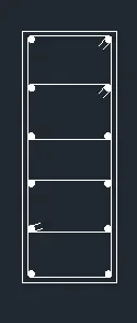
Drawing of column section c1a:
- Column of 9”x24” having 12 bar 16mm dia
- Draw a rectangle of 9”x24” by using command “REC”
- Now take the offset command and make an offset of 40mm or 0.5”
Drawing of reinforcement:
- Take the circle tangent, tangent, radius mark the point of tangent at top and side line of column and make a circle of radius 8mm
- Next take the mirror command give the mirror line then place the bar at bottom and other side of the column
- Take the fillet command give the radius 2” for all the 4 sides
- Now take the command “div” and give the segment value 5
- Next take the circle command and make bar of 12mm dia and place at marked point
- Take the mirror command and mirror it in other side
- Now take the hatch command and take the solid hatch and hatch all the reinforcement bars
Drawing of strips:
- Take the line mark the line from a right to left bar top and bottom
- To make the hooks mark the line right and left side of the bar and trim it now place it at by rotating at required angle
Step5:
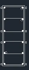
- Drawing of column section c2:
- Column of 9”x24” having 8 bar of 20mm dia and 4 bar of 12mm dia.
- Similarly follow the same process for this column as we did above
- Mark the “a” for the identification of 20mm bar
Step6:
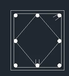
- Drawing of column section c2a:
- Column of 9”x10”” having 8 bar of 16mm dia and 4 bar of 12mm dia.
- Similarly follow the same process for this column as we did above
Step7:
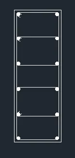
Drawing of column section c3:
- Column of 9”x25”” having 12 bar of 16mm dia and 4 bar of 12mm dia.
- Similarly follow the same process for this column as we did above
Result:
2):
Aim: To Create a window schedule
Introduction: To Create a window schedule by using Auto Cad
Procedure:
Step1:
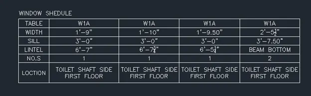
- Take the table command
- Draw a table with 5 columns and 6 rows
- Next enter the text in the data as required
3):
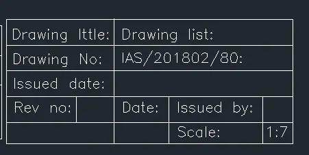
Aim: To create the drawing template
Introduction: To create the drawing template by using AutoCAD
Procedure:
Step1:
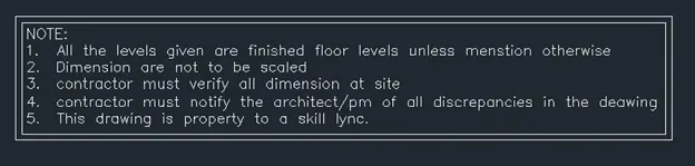
- Take rectangle by using command “REC”
- Next take the offset command and give the offset value as 0.5”
- Take mtext command and entre the required text
Step2:
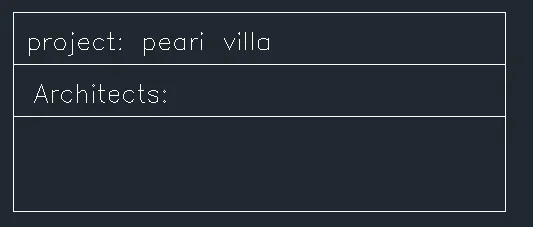
- Take rectangle by using command “REC”
- Next take the offset command and give the offset value as 2’
- Take mtext command and entre the required text
Step3:
- Take rectangle by using command “REC”
- Take a line command to make columns
- Take mtext command and entre the required text
Result:

4):
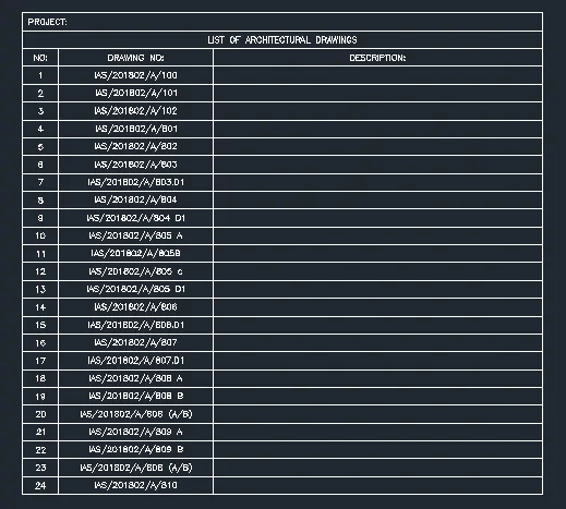
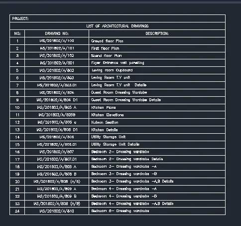
Aim: To create the list of drawing schedule
Introduction: To create the list of drawing schedule by using AutoCad
Procedure:
Step1:
- Take the command table or click on table icon from annotation bar
- Make the table as 24 rows and 3 columns 2 rows with tittle and one with data
- Now select the first point and drag the table with 2 point
- Now take the command “mtext” type the multiline text as required
Step2:
- Now take the command “mtext” type the multiline text as required
- Copy the text and edit the text
Result:
5):
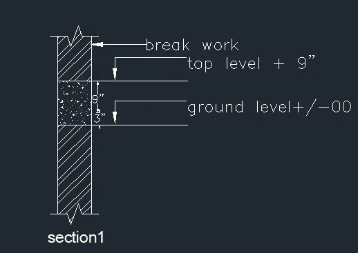
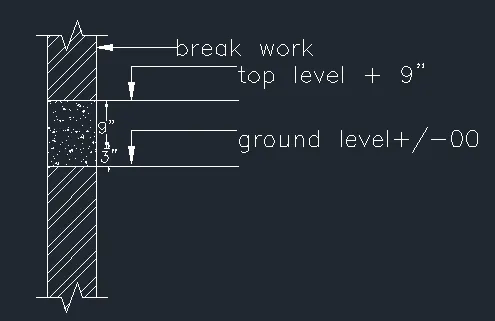
Aim: To create the Beam detail
Introduction: To create the Beam detail by using ActoCad
Procedure:
Step1:
- Take the command “rec” and draw a rectangle of 9”x4’
- mark a line 1’ from the top and take the offset command and make an offset of 9” from the 9” make another offset of 3” for ground level
Step2:
- Take the “BREAK LINE” command and break the line at top and bottom by selecting the 1st point 2nd point and break point
- Now take the command “HATCH” fill the hatch in the close boundary
- Take command “MTEXT” give the require text with leader
- Take the command “DIM” and give the dimensions
Result: