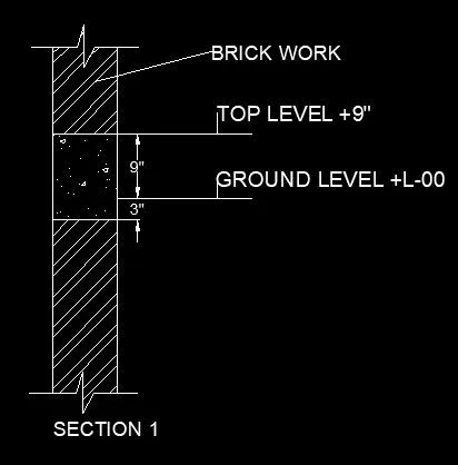
Creation of Column Schedule and Drawing Template using AutoCad
CREATION OF COLUMN SHEDULE & DRAWING TEMPLET USING AUTOCAD
Jagadeep.M.M
AIM:
To determine the creation of column shedule
Procedure:
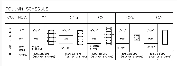
- Open autocad softwere, type QNew incommand box,press enter.
- Select default setting as imperial setting.
- Drawing units setting as length=(Engineering),precision=0'0.0", Ok
- Drawing limits setting as, specify the lower left corner=enter,upper right corner=100',100',enter.
- Type the command box Dimension style manager & press enter.
- enter modify-enter primary units-unit format=Engineering, precision=0'0.0",enter Ok.
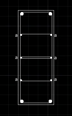
1)For column C1 draw a rectangle of 9"*24" having 20mm dia reinforcement at 4 corners of 12mm dia 6 reinforce ment bars in between connected by 8mm dia stirrup.
- Now we draw the a rectangle using the rectangle command using dimensions in the command box.
- by using offset command > 0.5" which will be the cover of concrete inside the offset.
- draw the reinforcement:by using circle command >selecting tan tan radius circle & give the radius of 0.4".
- Using the mirror command create the reinforcement on the bottom left side of column by giving plane as the midpoint of 2' line & click on NO for erase source object.
- Now using divide command>divide the 2' line into 4 segments.
- To make the point visible type "DDTYPE" in the command box & apply a suitable point.
- Now for reinforcement of 6number of 12mm dia.
- Now copy the circle using the top of the circle as the base point & place it on the point created by object snap.
- Place all the 3 circles on the each divided point & then delete the point created.
- create the similar circles on the right side by using mirror command.
- now draw the stirrups>connect the reinforcement 6mm with 1st row & 2nd row from top & bottom & 3rd from bottom.
- connect them as tangents of two circles.
- now use the hatch command fill the circles.
- now fillet the corners of the column with radius 0.5"
- Mark "a" for in between reinforcement to indicate it as12mm dia.
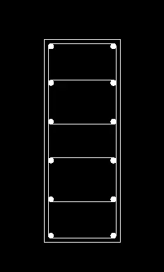
2)For column C1(a) draw a rectangle of 9"*24" having 16mm dia reinforcement at 12 corners of reinforcement bars in between connected by 8mm dia stirrup.
- Now we draw the a rectangle using the rectangle command using dimensions in the command box.
- by using offset command > 0.5" which will be the cover of concrete inside the offset.
- draw the reinforcement:by using circle command >selecting tan tan radius circle & give the radius of 0.4".
- Using the mirror command create the reinforcement on the bottom left side of column by giving plane as the midpoint of 2' line & click on NO for erase source object.
- Now using divide command>divide the 2' line into 5 segments.
- To make the point visible type "DDTYPE" in the command box & apply a suitable point.
- Now for reinforcement of 12number of 16mm dia.
- Now copy the circle using the top of the circle as the base point & place it on the point created by object snap.
- Place all the 6 circles on the each divided point & then delete the point created.
- create the similar circles on the right side by using mirror command.
- now draw the stirrups>connect the reinforcement 6mm with 1st row & 2nd row from top & bottom & 3rd row & 4th row from top & bottom.
- connect them as tangents of two circles.
- now use the hatch command fill the circles.
- now fillet the corners of the column with radius 0.3"
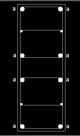
3)For column C2 draw a rectangle of 9"*24" having 20mm dia reinforcement at 8 corners of 12mm dia 4 corner &reinforce ment bars in between connected by 8mm dia stirrup.
- Now we draw the a rectangle using the rectangle command using dimensions in the command box.
- by using offset command > 0.5" which will be the cover of concrete inside the offset.
- draw the reinforcement:by using circle command >selecting tan tan radius circle & give the radius of 0.4".
- Using the mirror command create the reinforcement on the bottom left side of column by giving plane as the midpoint of 2' line & click on NO for erase source object.
- Now using divide command>divide the 2' line into 5 segments.
- To make the point visible type "DDTYPE" in the command box & apply a suitable point.
- Now for reinforcement of 6number of 12mm dia.
- Now copy the circle using the top of the circle as the base point & place it on the point created by object snap.
- Place all the circles on the each divided point & then delete the point created.
- create the similar circles on the right side by using mirror command.
- now draw the stirrups>connect the reinforcement 6mm with 1st row & 2nd row from top & bottom & 3rd from bottom.
- connect them as tangents of two circles.
- now use the hatch command fill the circles.
- now fillet the corners of the column with radius 0.4"
- Mark "a" for in between reinforcement to indicate it as20mm dia.
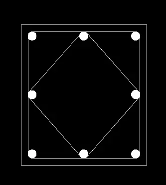
4)For column C2(a) draw a rectangle of 9"*10" having 16mm dia reinforcement at 8 corners & reinforcement bars in between connected by 8mm dia stirrup.
- Now we draw the a rectangle using the rectangle command using dimensions in the command box.
- by using offset command > 0.5" which will be the cover of concrete inside the offset.
- draw the reinforcement:by using circle command >selecting tan tan radius circle & give the radius of 0.3"
- Mirror these to the corner of the rectangle.
- Draw lines joining the midpoint of each side then by circle command give radius 0.3".
- Mirror the circle on opposit side using mirror command.
- now fillet the corner of the column radius 0.3"
- fill the reinforcement by hatch command.
5)For column C3 draw a rectangle of 9"*21" having 16mm dia reinforcement at 12 corners of reinforcement bars in between connected by 8mm dia stirrup.
- Now we draw the a rectangle using the rectangle command using dimensions in the command box.
- by using offset command > 0.5" which will be the cover of concrete inside the offset.
- draw the reinforcement:by using circle command >selecting tan tan radius circle & give the radius of 0.4".
- Using the mirror command create the reinforcement on the bottom left side of column by giving plane as the midpoint of 2' line & click on NO for erase source object.
- Now using divide command>divide the 2' line into 5 segments.
- To make the point visible type "DDTYPE" in the command box & apply a suitable point.
- Now for reinforcement of 12number of 16mm dia.
- Now copy the circle using the top of the circle as the base point & place it on the point created by object snap.
- Place all the 6 circles on the each divided point & then delete the point created.
- create the similar circles on the right side by using mirror command.
- now draw the stirrups>connect the reinforcement 6mm with 1st row & 2nd row from top & bottom & 3rd row & 4th row from top & bottom.
- connect them as tangents of two circles.
- now use the hatch command fill the circles.
- now fillet the corners of the column with radius 0.3".
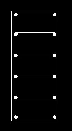
Table creating:
- Create a table by drawing a rectangle of 60'*13' & then explode it.
- By using the offset command : offset the 13' line by taking a distance of 5' & then offset the 60' line at a distance of 2' from bootom & top.
- Trim the extra line using trim command.
- Now we enter the text in the table by using singleline text from the text drop down menu.
- Specify the point of the text ,text height as 8" & text angle as 0 degree.
- By using the "ST" command we can change the style of the text from the font name as "romans.shx".
- Insert all the text on the respective rows & columns.
- give the heading as column schedule.
Results:

AIM:
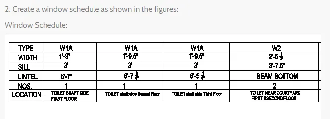
To Draw a window shedule
Procedure:
- Open autocad softwere, type QNew incommand box,press enter.
- Select default setting as imperial setting.
- Drawing units setting as length=(Engineering),precision=0'0.0", Ok
- Drawing limits setting as, specify the lower left corner=enter,upper right corner=100',100',enter.
- Type the command box Dimension style manager & press enter.
- enter modify-enter primary units-unit format=Engineering, precision=0'0.0",enter Ok.
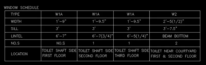
- Create a table by drawing a rectangle of 54'*14' & then explode it.
- By using the offset command : offset the 14' line by taking a distance of 10' & Last columns as14' offset & offset the 60' line at a distance of 2' from the rows & last rows give the offset of 4'.
- Trim the extra line using trim command.
- Now we enter the text in the table by using singleline text from the text drop down menu.
- Specify the point of the text ,text height as 8" & text angle as 0 degree.
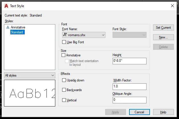
- By using the "ST" command we can change the style of the text from the font name as "romans.shx".
- Insert all the text on the respective rows & columns.
- give the heading as window schedule.
Results:
AIM:
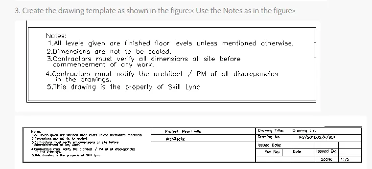
To create drawing temlate.
Procedure:
- Open autocad softwere, type QNew incommand box,press enter.
- Select default setting as imperial setting.
- Drawing units setting as length=(Engineering),precision=0'0.0", Ok
- Drawing limits setting as, specify the lower left corner=enter,upper right corner=100',100',enter.
- Type the command box Dimension style manager & press enter.
- enter modify-enter primary units-unit format=Engineering, precision=0'0.0",enter Ok.
- Create a table by drawing a rectangle of 46'*12' & then explode it.
- copy this rectangle & place in next to it with snap on & copy 2 of them.
- Divide the 2nd column of table into two & 3rd column into 5.
- by using the offset command with offset distance 2' select the object & create the rows.
- trim the unwnted lines.
- now we insert the text.
- Now we enter the text in the table by using singleline text from the text drop down menu.
- Specify the point of the text ,text height as 8" & text angle as 0 degree.
- By using the "ST" command we can change the style of the text from the font name as "romans.shx".
Results:

AIM:
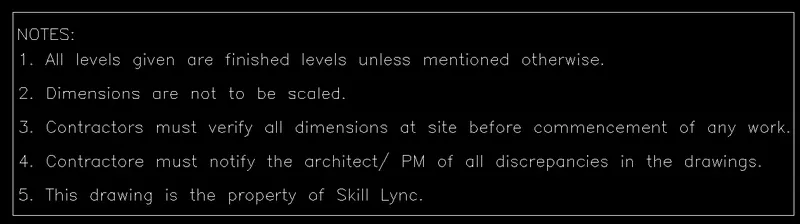
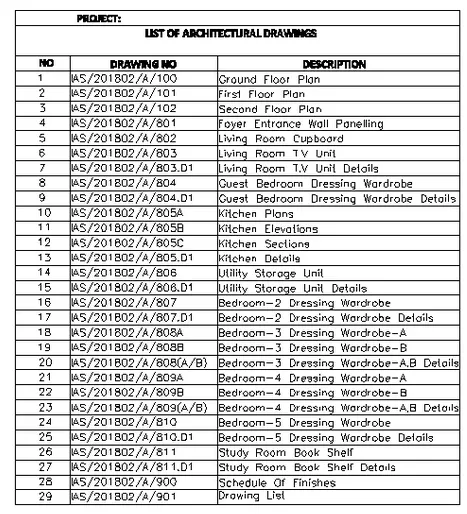
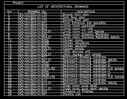
To create the list of drawing schedule.
Procedure:
- Open autocad softwere, type QNew incommand box,press enter.
- Select default setting as imperial setting.
- Drawing units setting as length=(Engineering),precision=0'0.0", Ok
- Drawing limits setting as, specify the lower left corner=enter,upper right corner=100',100',enter.
- Type the command box Dimension style manager & press enter.
- enter modify-enter primary units-unit format=Engineering, precision=0'0.0",enter Ok.
- Create a table by drawing a rectangle of 42'*33' & then explode it.
- Draw the columns by offset command with a distance of 5',15',20' from the top side.
- Create rows by offset by distance of 1',2',1' from the top side.
- use the trim command to remove the unwanted lines.
-
- now we insert the text.
- Now we enter the text in the table by using singleline text from the text drop down menu.
- Specify the point of the text ,text height as 8" & text angle as 0 degree.
- By using the "ST" command we can change the style of the text from the font name as "romans.shx".
Results:
AIM:
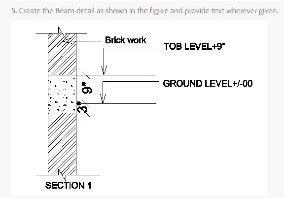
To draw the beam detail.
Procedure:
- Open autocad softwere, type QNew incommand box,press enter.
- Select default setting as imperial setting.
- Drawing units setting as length=(Engineering),precision=0'0.0", Ok
- Drawing limits setting as, specify the lower left corner=enter,upper right corner=100',100',enter.
- Type the command box Dimension style manager & press enter.
- enter modify-enter primary units-unit format=Engineering, precision=0'0.0",enter Ok.
- Draw a cross-section of beam with height 4' & thickness 9".
- with the line command draw a line of 4' in +Y direction then 9" in +X direction & 4' downward & close.
- Give an offset top of the 9" wall, give the offset of 1'& again 1' give the offset.
- Hatch the portion of brick & concrete in the hatch tools.
- select the leader from the annotation tab & write the text height of 2".
- use the single text command.
Results: