Creation of Column Schedule and Drawing Template using AutoCad
1. COLUMN SCHEDULE:
AIM:
To create column schedule with the help of lines and single line text command.
INTRODUCTION:
AutoCAD is a computer aided design software and drafting software application.
AutoCAD is used in industry by:
Engineers (Civil / Mechanical / Electrical)
Architects
Graphic Designers
City Planners and
Other Professionals
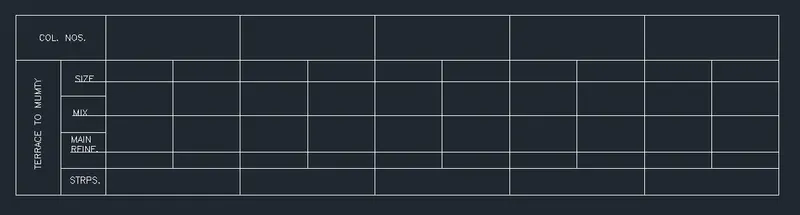
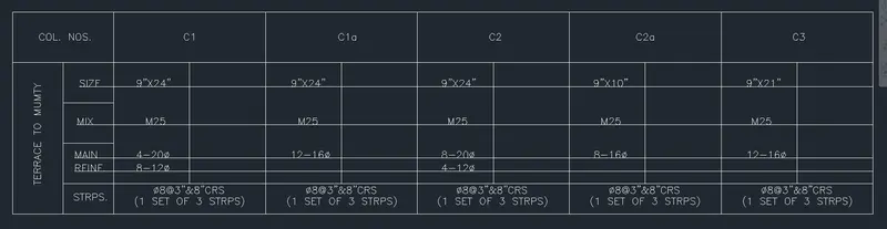
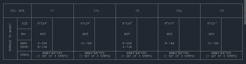
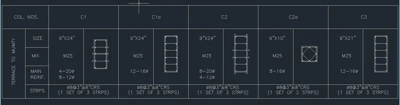
In this project, I have done column scheduling using AutoCAD software. All details are mentioned in the column scheduling like No. of columns, Column names, their sizes, concrete mix, main reinforcement nos. and sizes and stirrups.
In this project, we will discuss about the procedure how column scheduling is done.
PROCEDURE:
- Open AutoCAD software
- Start from scratch
- Choose Engineering units
- Specify the limits as lower left corner (0,0) and upper right corner (100’,100’)
- Go to
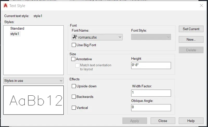
< Annotate
< manage text styles
< Create new style 1
< Choose font as romans.shx
< set text height to 8”
< Apply
< Set current
< Close.
- Use the command Dtext or Single line text to create the words.
- Invoke
< Command Dtext
< Specify the start
< Justify as Left
< Mention the rotation angle as 0 degree for horizontal text, 90 degrees for vertical text or give any required angle and press enter
< and start typing the text.
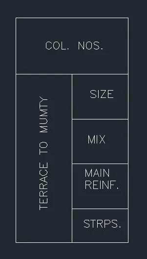
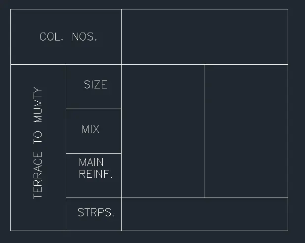
- Using the line command, a suitable table is created to fit in the words perfectly.
- Reference lines are created at necessary places to align the words perfectly in the table.
- After completion, the reference lines are trimmed.
- If there are any mistakes in the words, it can be edited using the command ED(TextEdit).
- Also, spell check can be done.
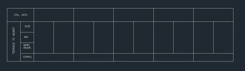
RESULT:
2. WINDOW SCHEDULE:
AIM:
To create window schedule with the help of lines and single line text command.
INTRODUCTION:
AutoCAD is a computer aided design software and drafting software application.
AutoCAD is used in industry by:
Engineers (Civil / Mechanical / Electrical)
Architects
Graphic Designers
City Planners and
Other Professionals
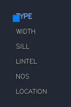
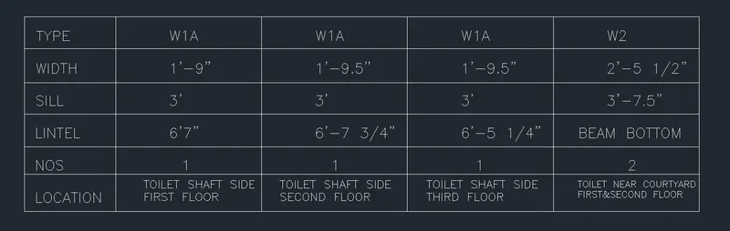
In this project, I have done Window scheduling using AutoCAD software. All details are mentioned in the window scheduling like No. of windows, Type of windows, Width of each window, Height of Sill level, Height of Lintel level and its Location.
In this project, we will discuss about the procedure how window scheduling is done.
PROCEDURE:
- Open AutoCAD software
- Start from scratch
- Choose Engineering units
- Specify the limits as lower left corner (0,0) and upper right corner (100’,100’)
- Go to
< Annotate
< manage text styles
< Create new style 1
< Choose font as romans.shx
< set text height to 8”
< Apply
< Set current
< Close.
- Use the command Dtext or Single line text to create the words.
- Invoke
< Command Dtext
< Specify the start
< Justify as Left
< Mention the rotation angle as 0 degree for horizontal text, 90 degrees for vertical text or give any required angle and press enter
< and start typing the text.
- Using the line command, a suitable table is created to fit in the words perfectly.
- Reference lines are created at necessary places to align the words perfectly in the table.
- After completion, the reference lines are trimmed.
- If there are any mistakes in the words, it can be edited using the command ED(TextEdit).
- Also, spell check can be done.
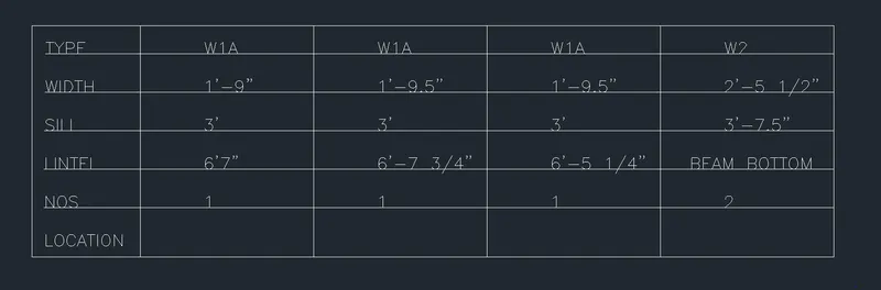
- Here, the scale factor is reduced to 0.8 to fit inside the table.
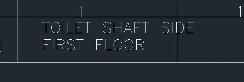
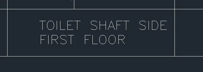
- In this, the scale factor is further more reduced to 0.6 to fit inside the box since it is a long text.


RESULT:
3. DRAWING TEMPLATE
AIM:
To create drawing template with the help of lines and single line text command.
INTRODUCTION:
AutoCAD is a computer aided design software and drafting software application.
AutoCAD is used in industry by:
Engineers (Civil / Mechanical / Electrical)
Architects
Graphic Designers
City Planners and
Other Professionals
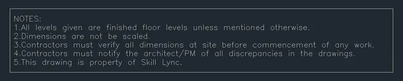
In this project, I have done Drawing template using AutoCAD software. All details are mentioned in the drawing template like Notes, Project name, Architects name, Drawing title, Drawing No., Revision No., Issued date, Issued by and Scale.
In this project, we will discuss about the procedure how drawing template is done.
PROCEDURE:
- Open AutoCAD software
- Start from scratch
- Choose Engineering units
- Specify the limits as lower left corner (0,0) and upper right corner (100’,100’)
- Go to
< Annotate
< manage text styles
< Create new style 1
< Choose font as romans.shx
< set text height to 8”
< Apply
< Set current
< Close.
- Use the command Dtext or Single line text to create the words.
- Invoke
< Command Dtext
< Specify the start
< Justify as Left
< Mention the rotation angle as 0 degree for horizontal text, 90 degrees for vertical text or give any required angle and press enter
< and start typing the text.
- Use the command Mtext or Multi-line text to create a set of sentences or a para.
- Invoke
< Command Mtext
< Specify the start
< Justify as Left(TL)
< Mention the rotation angle as 0 degree for horizontal text, 90 degrees for vertical text or give any required angle and press enter
< and start typing the text.
- Using the line command, a suitable table is created to fit in the words perfectly.
- Reference lines are created at necessary places to align the words perfectly in the table.
- After completion, the reference lines are trimmed.
- If there are any mistakes in the words, it can be edited using the command ED(TextEdit).
- Also, spell check can be done.
RESULT:

4. DRAWING SCHEDULE
AIM:
To create drawing schedule with the help of lines and single line text command.
INTRODUCTION:
AutoCAD is a computer aided design software and drafting software application.
AutoCAD is used in industry by:
Engineers (Civil / Mechanical / Electrical)
Architects
Graphic Designers
City Planners and
Other Professionals
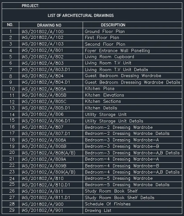
In this project, I have done Drawing schedule using AutoCAD software. All details are mentioned in the drawing schedule like the No.of drawings, code of each drawing and the description of each drawing individually.
In this project, we will discuss about the procedure how Drawing schedule is done.
PROCEDURE:
- Open AutoCAD software
- Start from scratch
- Choose Engineering units
- Specify the limits as lower left corner (0,0) and upper right corner (100’,100’)
- Create two text styles, one for headings in bold and other one for regular contents.
- Go to
< Annotate
< manage text styles
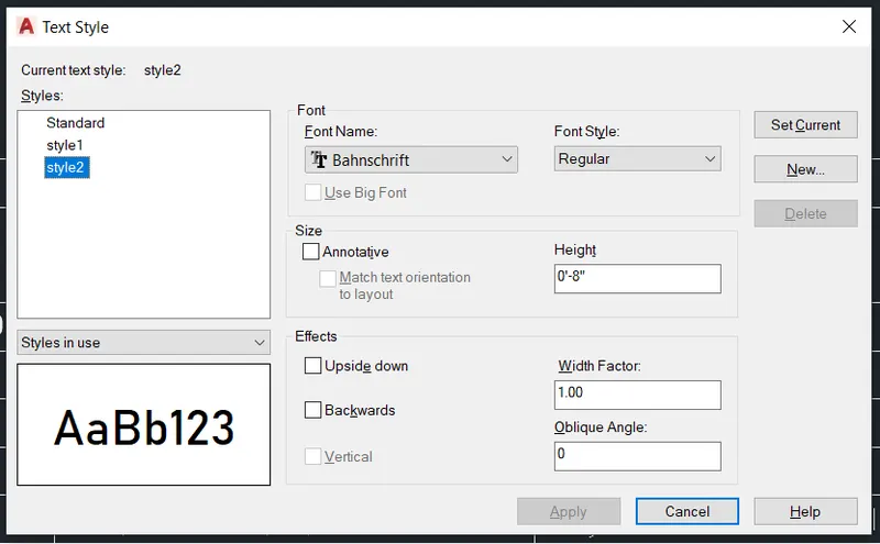
< Create new Style 2.
< Choose font as Bahnschrift
< set text height to 8”
< Apply
< Set current
< Close.

- Go to
<Annotate
< manage text styles
< Create new style 1
< Choose font as romans.shx
< set text height to 8”
< Apply
< Set current
< Close.
- Use the command Dtext or Single line text to create the words.
- Invoke
< Command Dtext
< Specify the start
< Justify as Left
< Mention the rotation angle as 0 degree for horizontal text, 90 degrees for vertical text or give any required angle and press enter
< and start typing the text.
- Using the line command, a suitable table is created to fit in the words perfectly.
- Reference lines are created at necessary places to align the words perfectly in the table.
- After completion, the reference lines are trimmed.
- If there are any mistakes in the words, it can be edited using the command ED(TextEdit).
- Also, spell check can be done.
RESULT:
5. BEAM DETAIL
AIM:
To create a beam detail with the help of lines, hatch, multi-leader and single line text command.
INTRODUCTION:
AutoCAD is a computer aided design software and drafting software application.
AutoCAD is used in industry by:
Engineers (Civil / Mechanical / Electrical)
Architects
Graphic Designers
City Planners and
Other Professionals
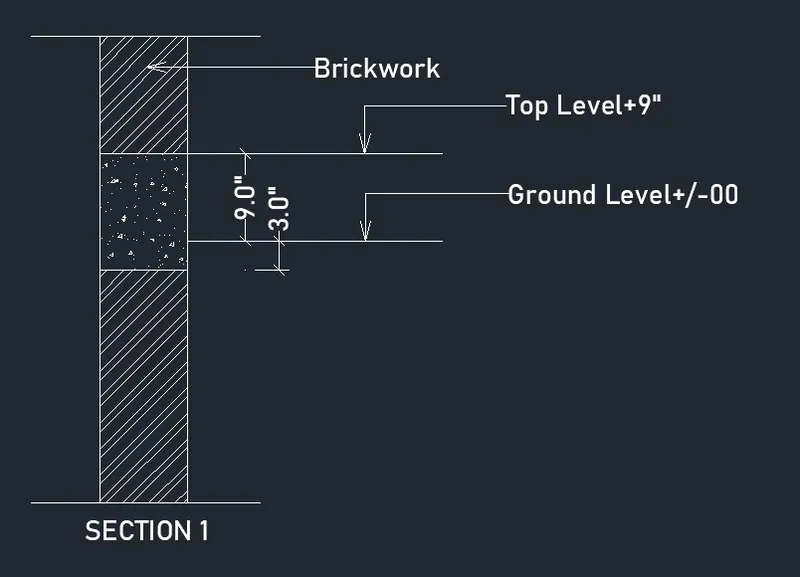
In this project, I have done beam detailing using AutoCAD software. All details are mentioned in the beam detail like the ground level, top level, sizes, brickwork.
In this project, we will discuss about the procedure how beam detail is done.
PROCEDURE:
- Open AutoCAD software
- Start from scratch
- Choose Engineering units
- Specify the limits as lower left corner (0,0) and upper right corner (100’,100’)
- Go to
< Annotate
< manage text styles
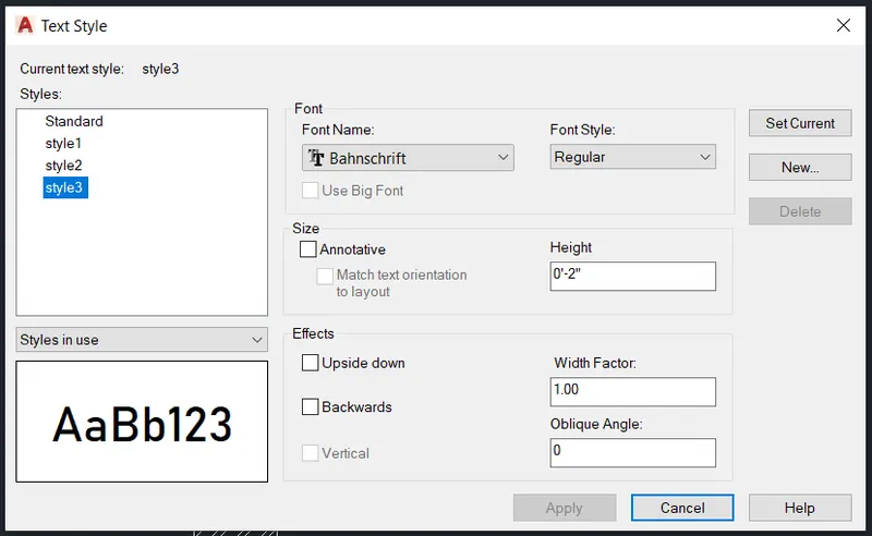
< Create new Style 3.
< Choose font as Bahnschrift
< set text height to 2”
< Apply
< Set current
< Close.
- Create a section of brickwork and beam 12" using lines and offset command.
- Invoke
< Hatch command
< Choose ANSI32
< Fill the brickwork area
< Increase the scale to 5 for better viewing
< close.
- Again, Invoke
< Hatch command
< Choose AR-CONC
< Fill the beam area
< Increase the scale to 0.50 for better viewing
< Close.
- Using DIMLIN Command, mark the beam dimensions, ground level and top level.
- Using Dtext command, mention as Section 1 in bottom.
- Go to
< Multi-leader
< Manage multi-leader styles
< Create New style and name it. I have made it as copy of standard.
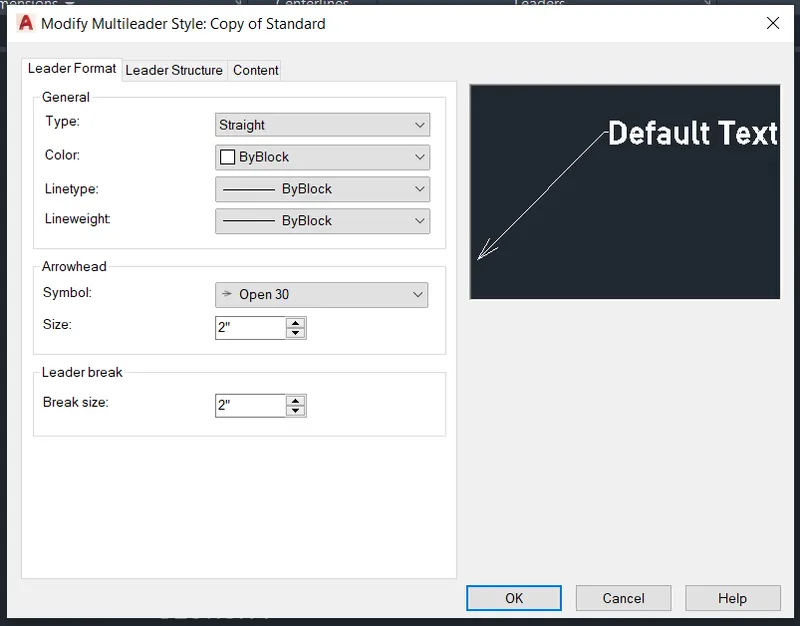
< Select Leader Format
- Choose arrowhead symbol as (Open 30)
- Make the size as 2", break size also as 2" and next
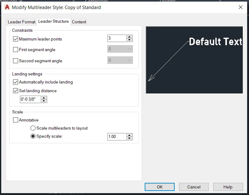
< Select Leader Structure
- Increase Max.Leader points to 3
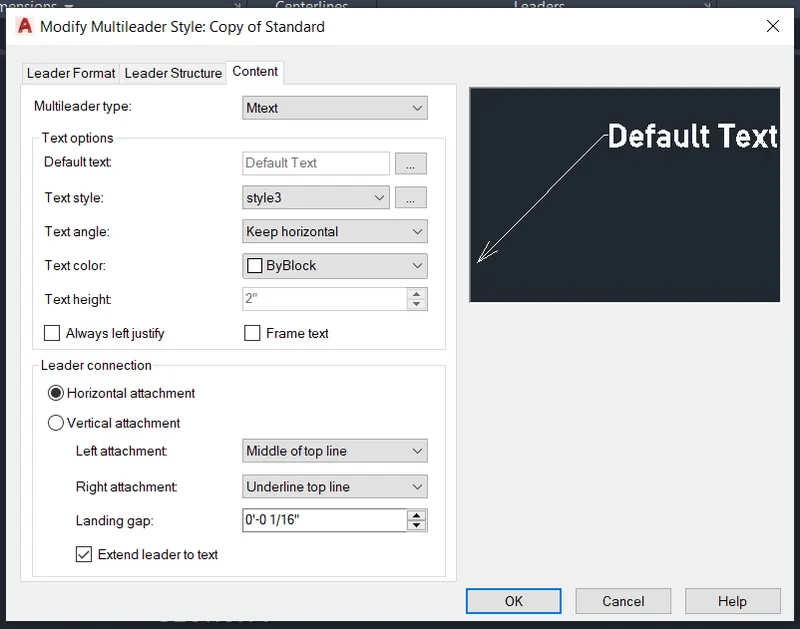
< Select Content
- Choose Text Style as (Style 3) which was already created which has a text height of 2" and font as Bahnschrift.
< Select Ok to apply and close.
RESULT: