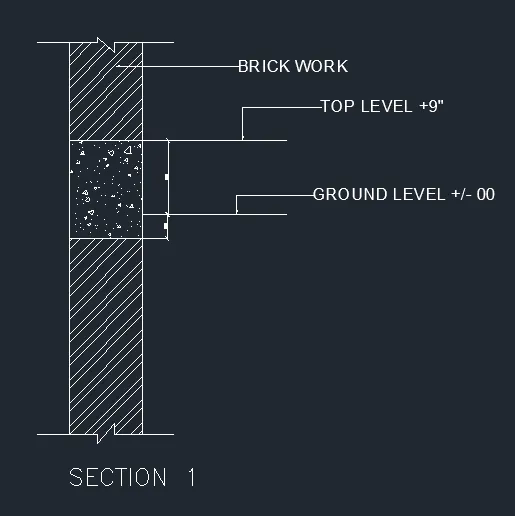
Creation of Column Schedule and Drawing Template using AutoCad
Creation of Column Schedule and Drawing Templete using AutoCad.
1. COLUMN SCHEDULE:
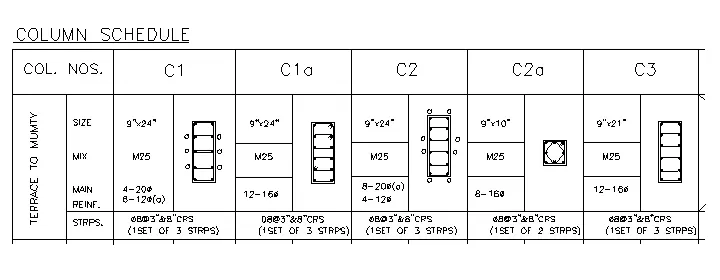
AIM: To Create a Column Schedule with the help of lines as Shown in the Figure above in the AutoCad.
INTRODUCTION: The Desired Column Schedule is Created in AutoCad using Primarily the line and text tool.The Procedure of drawing is explained in detail with diagrams of each step and the final result is given.
PROCEDURE:
STEP 1
- First I Selected the table and set the Columns and rows as per requirement.
- After i used merge command for adjusting tables cell Styles and Sizes.
STEP 2
- I used Multitext to Write the details of columns in Cells.
- I used Symbols for Some Mathematical functions in Column details.
STEP 3
- I used LINE, RECTANGULAR Commands for to draw the Stirrups.
- Commands are Used OFFSET,LINE,RECTANGULAR,P EDIT.
- Fillet for Stirrups Corner Curves, Radius , Dia. of the Bar and Multilines.
- I used Polyline Command for to increase the Width of the line for dia of the bars and hooks 10d.
STEP 4
- All Stirrups are move in to the Cells as per Column Nos.
- I used Text Command for to give all details.
- Table Method in tool palettes is very simple method to make a Column Schedule.
RESULT:
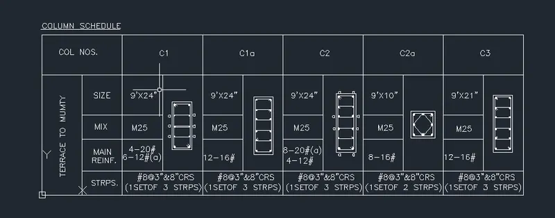
2. WINDOW SCHEDULE:
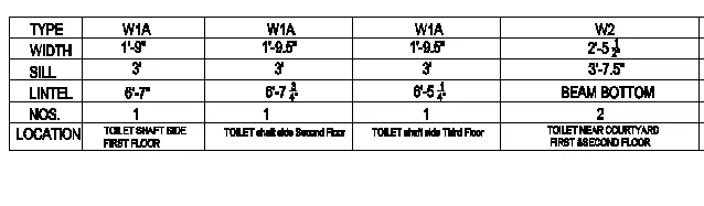
AIM: To Create a Window Schedule with the help of Table and Text Command as Shown in the Figure above in the AutoCad.
INTRODUCTION: The Desired Window Schedule is Created in AutoCad using Primarily the Table and text tool.The Procedure of drawing is explained in detail with diagrams of each step and the final result is given.
PROCEDURE:
STEP 1
- First I Selected the table and set the Windows and rows as per requirement.
- After i used merge command for adjusting tables cell Styles and Sizes.
STEP 2
- I used Multitext to Write the details of Windows in Cells.
- I used Symbols for Some Mathematical functions in Windows details.
STEP 3
- All Stirrups are move in to the Cells as per Column Nos.
- I used Text Command for to give all details.
- Table Method in tool palettes is very simple method to make a Window Schedule.
- Commands are Used tool palettes for table, text, text edit.
RESULT:
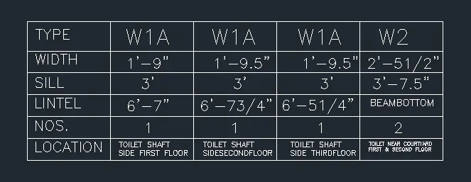
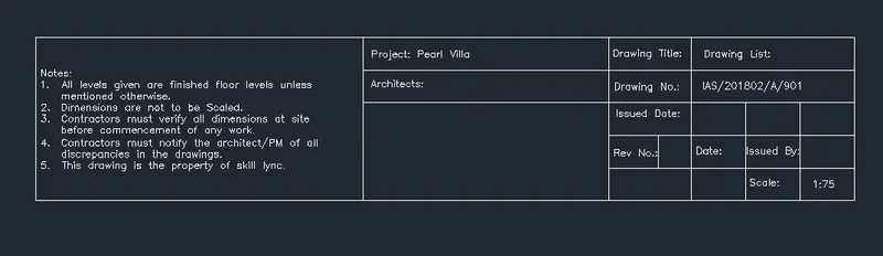
3. DRAWING TEMPLETE:
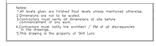

AIM: To Create the drawing templete with the help of line, rectangle and text Command as Shown in the Figure above in the AutoCad.
INTRODUCTION: The Desired drawing templete is Created in AutoCad using Primarily the line and text tool.The Procedure of drawing is explained in detail with diagrams of each step and the final result is given.
PROCEDURE:
STEP 1
- First I Selected the table and set the templetes and rows as per requirement.
- After i used merge command for adjusting tables cell Styles and Sizes.
STEP 2
- I used Multitext to Write the details of templetes in Cells.
- I used Symbols for Some Mathematical functions in templetes details.
STEP 3
- Notes are wrote in multitext and that notes are Copy paste in the table cells.
- Table Method in tool palettes is very simple method to make a templete.
- Commands are Used tool palettes for table, text, text edit.
RESULT:
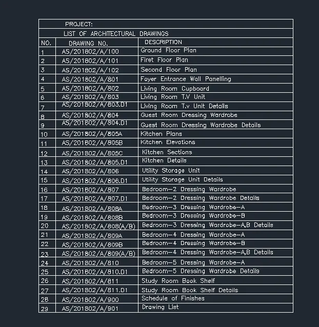
4. List of Drawing Schedule:
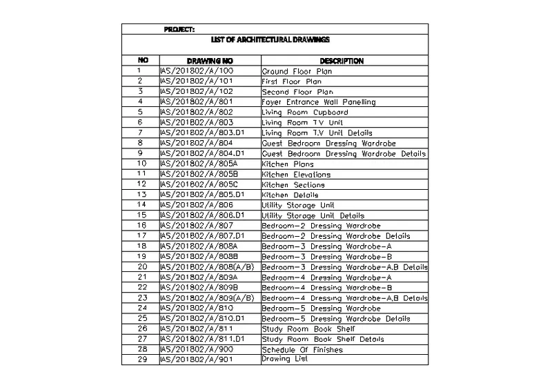
AIM: To Create the list of drawing Schedule with the help of Table and text Command as Shown in the Figure above in the AutoCad.
INTRODUCTION: The Desired list of drawing is Created in AutoCad using Primarily the Table and text tool.The Procedure of drawing is explained in detail with diagrams of each step and the final result is given.
PROCEDURE:
STEP 1
- First I Selected the table and set the drawing Schedule and rows as per requirement.
- After i used merge command for adjusting tables cell Styles and Sizes.
STEP 2
- I used Multitext to Write the details of drawing Schedule in Cells.
- I used Symbols for Some Mathematical functions in drawing Schedule details.
STEP 3
- Table Method in tool palettes is very simple method to make a templete.
- Commands are Used tool palettes for table, text, text edit.
RESULT:
5. Beam Detail:
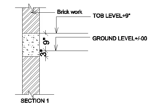
AIM: To Create the beam detail with the help of line Command as Shown in the Figure above in the AutoCad.
INTRODUCTION: The Desired beam detail is Created in AutoCad using Primarily the line tool.The Procedure of drawing is explained in detail with diagrams of each step and the final result is given.
PROCEDURE:
STEP 1
- First Set the Drawing limits, Units, dimstyle,units to engineering inches.
STEP 2
- I used the line Command for to draw the cross section of given Wall.
STEP 3
- I used Hatch Command for Walls and Concrete for lintels with adjustment of properties to Clear visible of hatches.
- I used dimension Line for to measure the Dimensions.
STEP 4
- I used Leaders Command also for to write the description of masonary and Levels.
- I used multi text Command for to write the section details.
- Commands Used Line, Dimline, text, leaders,hatch.
RESULT: