Creating Walls, Partition walls and Floors for a residential layout using REVIT
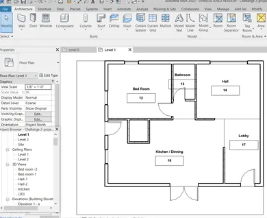
1) Use the project file created from Week 2. Use it for this assignment. Based on your layout from week 2, using floor tool under architecture tab and select the floor with appropriate material and thickness using the property browser create a layout in the Ground floor Level. Align the floor plan with grids created from week 2
ANS:
Aim: create a layout in the Ground floor Level as similar created in project-2 in Revit.
Tools Used: Manage toolbar, Project information etc.
Procedure:
- In Revit, click the File Ribbon tab, hover the mouse over New, and then select Project.
- Select the Architectural template is in list of Project Templates, click Browse.
- In the Choose Template dialog box, navigate to the. rte file you've been working in.Click OK.
- The new "project" and give name as project 3
- Save the project. and copy the old project 2
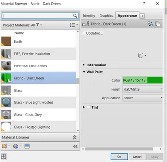
- Click Manage tab Settings panel Materials.
- In the Material Browser, select the material to change in the project materials list.
- In the Material Editor panel, click the Appearance tab and do the following
- To save the changes to the material, click Apply.
- On the ribbon, click (Grid). Architecture tab, Datum panel(Grid), Structure tab Datum panel (Grid)
- Click Modify | Place Grid tab Draw panel and select a sketch option.
- Use (Pick Lines) to snap the grid to an existing line, such as a wall.
- (Optional) Click Modify | Place Grid tab Draw panel(multi-Segment) to sketch grids requiring more than one segment.
- Click when the grid is the correct length.
- Revit automatically numbers each grid. To change the grid number, click the number, enter the new value, and press ENTER.
- You can use letters for grid line values. If you change the first grid number to a letter, all subsequent grid lines update appropriately.
- As you draw grid lines, the heads and tails of the lines can align to one another.
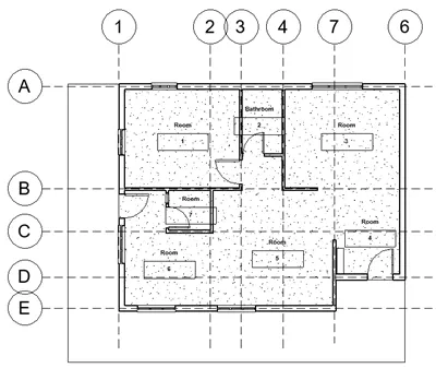
- In the Architecture tab > Build panel, click Door and windows.
- To insert a tag with each door or window, verify that Tag on Placement is toggled on.
- You can specify the tag options using the Options Bar.
- Load door families.
- Use the Type Selector to change door types.
- Place doors in the model.
- Use the space bar to change the swing of the door before placing the door.
- Use the flip controls to change the orientation of the door after placing it.
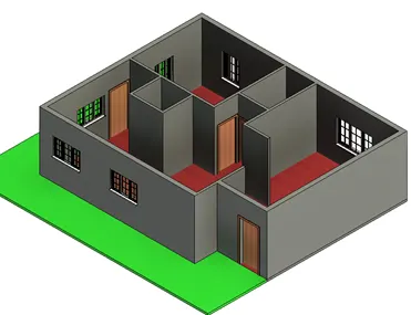
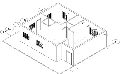
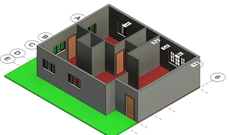
Result: Residential unit is Created along with the properties added to the walls and fllors is done and 3d view is shown.
2) Add walls based on the floor layout. Pick lines or use the draw tool to modify the boundary of walls. Use the property browser to select appropriate material and thickness for walls. After creating the walls verify using the property browser to see if the top and bottom of the walls are constrained.
a. Based on your observation, what is beneficial for connecting walls with associated levels rather than being Unconnected
b. Which option is convenient for modeling walls, By Height or By Depth?
ANS:
Aim: Creating a or Add walls based on the floor layout. in Revit.
Tools Used: Architecture toolbar, Wall, Trim, Join etc.,
Procedure:
- Open a floor plan view or a 3D view.
- Click Architecture tab then Build panel then Wall drop-down
- If you want to place a wall type other than the one displayed in the Type Selector, select a different type from the drop-down.
- You can use the bottom part of the Properties palette to modify some of the instance properties for the selected wall type before you start placing instances.
- On the Options Bar, specify the following:
- (3D views only) Select a level for the wall’s base constraint. You can choose a non-story level. See levels.
- Select a level for the wall’s top constraint, or enter a value for the default setting of Unconnected. See height and width.
- In the Material Editor panel, click the Graphics tab.
- To change how the material looks in shaded views (such as 3D views and elevations), under Shading, do the following:
- If you want to use the render appearance to represent the material in shaded views, select Use Render Appearance for Shading.
a. Based on your observation, what is beneficial for connecting walls with associated levels rather than being Unconnected
When creating an architectural wall or a structural wall, you can specify the following properties on the Options Bar:
Level (for 3D views), Depth/Height, Top Constraint, Unconnected Height.
- Use these properties together with Base Constraint to control whether the wall is drawn from a specified level upwards or downwards,
- the height of the wall, and whether its height will change when its base constraint or top constraint moves.
b. Which option is convenient for modeling walls, By Height or By Depth?
- When you create a wall in a plan view, the Base Constraint is the level associated with the view. When you create a wall in a 3D view,
- use Level on the Options Bar to specify the level to use for the wall's Base Constraint value.
- When you use Depth on the Options Bar, use a structural plan to see
- the walls extending downward from the current level, or modify the view range of a floor plan to make them visible.
- The following image shows a section view of 4 walls created using different height/depth
- settings with a Base Constraint of L-1 (Level 1). The table below shows the properties of each wall.
Result: walls have been created and with proper properies and constrained and the properties of wall type is also discussed and 3d view is shown.
3) Copy the model elements ( wall, floor ) modelled to Ground Floor Level and paste it aligned to First Floor Level . Use modify tab to utilize copy and paste options to align
elements to a different level
ANS:
Aim: Copying the model elements ( wall, floor ) modelled to Ground Floor Level and paste it aligned to First Floor Level in Revit.
Tools Used: Architecture toolbar , copy etc.,
Procedure:
- Select elements to be copied in the active view (plan, section/elevation or 3D view).
- Some hosting elements (like walls) will automatically include the hosted elements.
- However, if this is not working, then manually select the hosted elements to copy them.
- copy to clipboard (CTRL+C) or from the Modify ribbon>Clipboard panel, choose Copy
- On the Modify ribbon > Clipboard, click the drop-down arrow under the Paste command
- Select "Aligned to Selected Levels"
- Choose the Target level (i.e., Level 2)
- Switch to a 3D View to see the results.
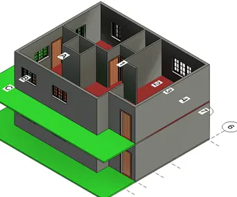
Result: Residential unit is Created, Doors and Windows are installed and 3d view is shown.
4) Use interior partition walls to create separate rooms within your residential unit. The model must include the following rooms
a. Living Room/ Drawing Room ( 15’ X 18’)
b. Dining Room (9’ X 11’)
c. Bed Room ( 9’ X 12’ and 15’ X 11’)
d. Rest Room ( 10’ X 12’ )
e. Kitchen (8’ X 10’)
The above are for examples. You can use them or use your measured entities to create your model based on your layout. You may include entry walkway, Patios or Guest
rooms based on your creativity and purpose of modeling. Convert units if you are using metric system
ANS:
Aim: Creating interior partition walls to create separate rooms within your residential unit in Revit.
Tools Used: Architecture toolbar , Wall, Trim, Join, copy etc.,
Procedure:
- Open a floor plan view or a 3D view.
- Click Architecture tab then Build panel then Wall drop-down
- If you want to place a wall type other than the one displayed in the Type Selector, select a different type from the drop-down.
- You can use the bottom part of the Properties palette to modify some of the instance properties for the selected wall type before you start placing instances.
- On the Options Bar, specify the following:
- (3D views only) Select a level for the wall’s base constraint. You can choose a non-story level. See levels.
- Select a level for the wall’s top constraint, or enter a value for the default setting of Unconnected. See height and width.
Result: Residential unit is Created, and copied at the level 2 using paste option and 3d view is shown.
5) Based on week 2 assignment, the components to be included in a residential unit were inserted to the Revit file. Place these components in appropriate locations to add details to your residential model
a. Place Doors and windows in the wall at appropriate locations
b. The Living Room must include furniture set, couch table and TV desk and shelf cabinets
c. The Dining Room must include a table and chairs serving the purpose of eating
d. Bed Room must include a bed set, shelf, lighting and individual study desk and chair
e. Rest room should include bath tub and plumbing fixtures discussed in class
f. Kitchen should include countertops, gas stove cabinet and shelves to store food items
g. The wash/storage room can include washing machines and shelves to store clothes
All the components are available in Revit Library. Use them to place at appropriate locations to add details to your model. Use 3D navigation to check the model and its authenticity on a real time basis to verify the model
ANS:
Aim: Creating the furnuture and other component in the Builting created in project 2. in Revit.
Tools Used: Insert toolbar, Load Family. etc.,
Procedure:
- Click Insert tab then Load from Library panel (Load Family).
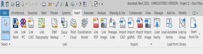
- In the Load Family dialog, double-click the category of the family that you want to load. In this case use us Family.
- Preview any of the families in the category: To preview a single family, select it from the list.
- At the top right of the dialog, under Preview, a thumbnail image of the family displays.
- To display a thumbnail image in the list for all families in the category, at the top right corner of the dialog, click Views
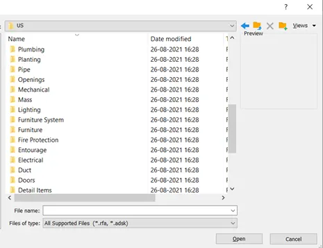
- Select the family that you want to load, and click Open.
- The family type is now available to place in the project.
- It displays in the appropriate category under Families in the Project Browser.
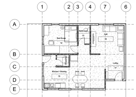
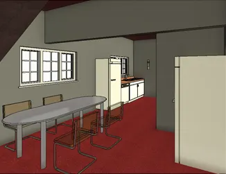
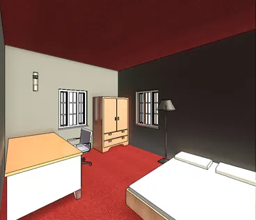
- In Realistic View Each and every rooms images were attached like Wise,
- Kitchen Room:
- Bed Room
- Rest Room
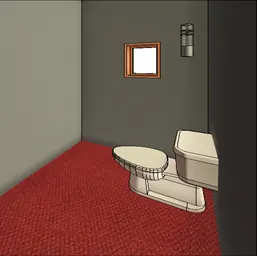
- Hall
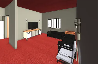
- Wash Room
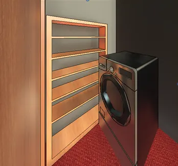
- Over all 3d View
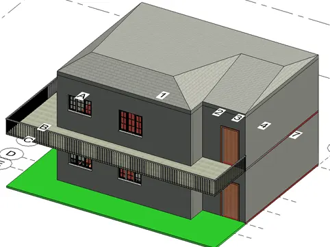
Result: Residential unit is Created, Doors and Windows are installed and 3d view of all the components of the residential unit is shown.