Creating Walls, Partition walls and Floors for a residential layout using REVIT
1.AIM
To draw the floor plan layout with aligning of GRIDS by using the REVIT Software.
PROCEDURE
- To create a new page with Imperial architectural .
- To save file at appropriate name.
- To create a conceptual layout of residential unit of our plan.
- First to desire the acquired land area of site and to measure the layout area of entire residential area.
- To create the layout of the residential building with the detailed level of designed building.
- Through architecture, to create the room with appropriate and to separate the area of the particular area to splitted.
- Choose , Door to add the particular plan for wherever we want for single flush door .
- If we want Double flush door, from to get the templates from our storage of comments at the tool of LOAD FAMILY.
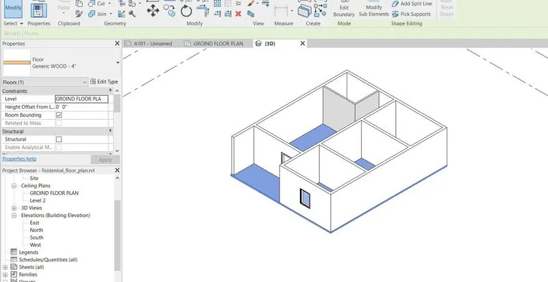
- Take ,, FLOOR’ this tool to create the floor level at plinth level of residential building, in which it has taken under Architecture tab.
- After created the boundary, then click to tick have to created the floor@12 inch of thickness by automatically.
- It has to changes of our requirement standard, to select the floor in 3D view then goes to select the EDIT type on right side top of properties.
- This comes after to create the duplicate file for whatever thickness we need and also to edit the structure with standard thickness with required categories of structure, for here I choosen to PLYWOOD flooring.
- GRID - Grid lines are finite planes. This allows you to determine whether grid lines appear in each new plan view that you create for a project.
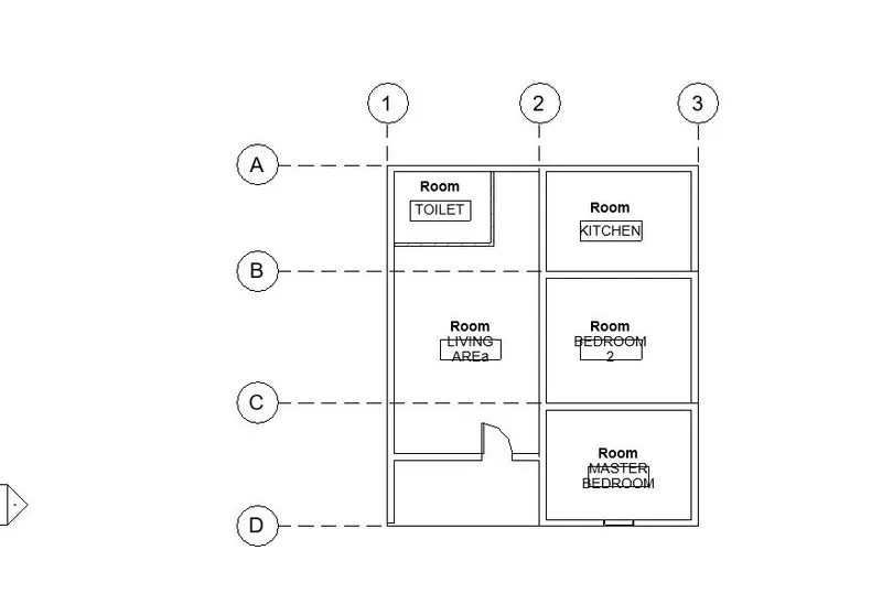
- Have to select the ‘GRID ‘ to making the construction layout for plan.
- Here, we given Grids in Transverse of the name in A,B,C,D,E @ distance of Our standard convenient.
- Similarly to Longitudinal Grids from 1 to 3.
RESULTS
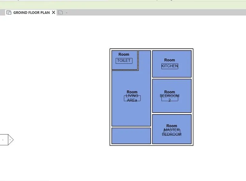
This Design and Modeling of Layout with grids is drawn by using the Revit Software.
2.AIM
To create a floor plan and need to apply the materials and thickness using the property browser for walls.
PROCEDURE
- To create a wall with proper height.
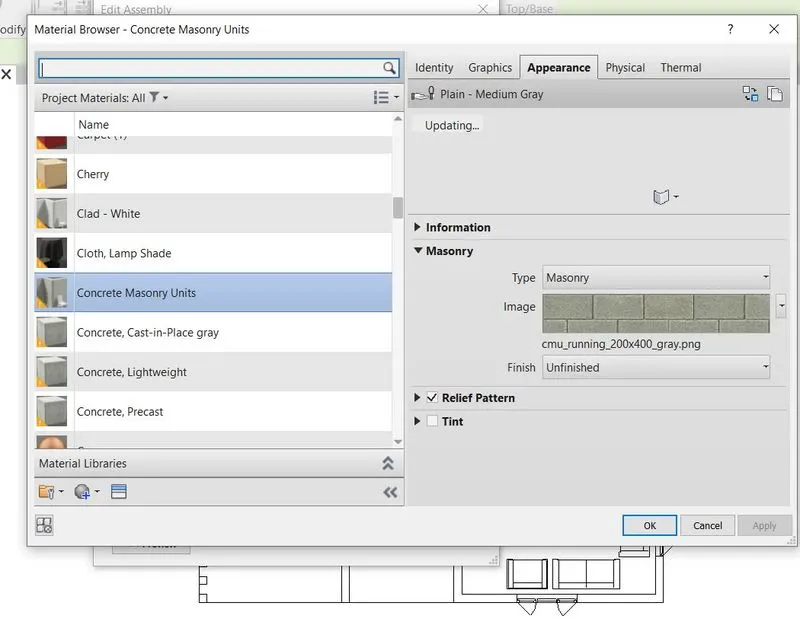
- After we select the wall, click the edit type from the properties browser.
- Click the edit type, to change the materials type as Brick, Soldier course.
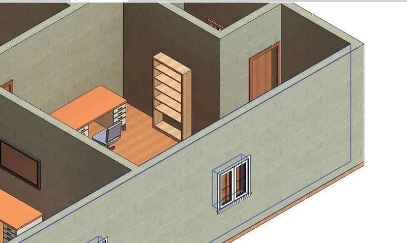
Beneficial of Connecting Walls
- The walls are connected to our current level to desired height , it helps to automatically visualize the starting ,ending, cutting point in Parametric view.
- If we select the top constraint as upto level : Level – 2, the height of the wall changes with the levels.
- When we put the level height of 10’ then height of the wall is also changes to the 10’.
- After creating the wall , to change the dimensions and thickness by using properties.
- The walls are constrained at top level and bottom level.
- In sectional view, have proper wall connection is aligned.
- The walls are unconnected at top and bottom like roof and floor, its useful to identify the wall properties and layer.
By Height is to Convenient of Modeling
- By Height is most convenient of modeling, because of draw a wall in 2D plan view its directly convert to 3D view by showing same height have mentioned on 2D.
- Architecture will understand that when a level changes its height, the wall too need to change. So we decide to height for modeling.
3.AIM
To create a Model of Ground floor elements to aligned the First floor level by using the various tools of Revit Software.
PROCEDURE
- To created the Ground floor plan has to included all model elements of Wall, Door, Widows, Rooms, similar to components of all categories with required families and elements.
- After that, we have to create the next level of building for same ground level to First floor level.
- Before we create the level 2 for first floor level from 10 feet to 20 feet @ Elevation view.
- Then, have go to Ground floor plan.
- Select the whole layout of Ground floor plan then copied the selected areas.
- To choose the next level of Level 2, on that to paste the layout of level 2.
- To check the 3D view for proper visualization of G+1 elevational view.
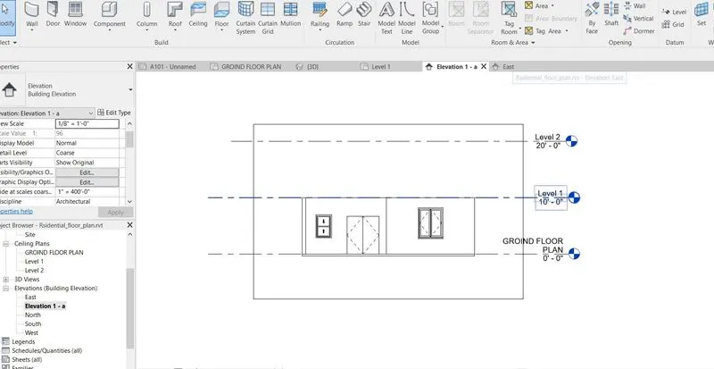
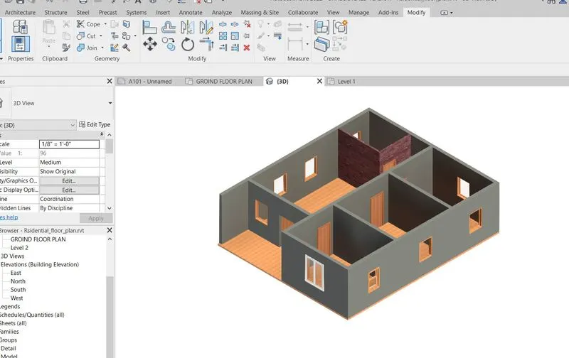
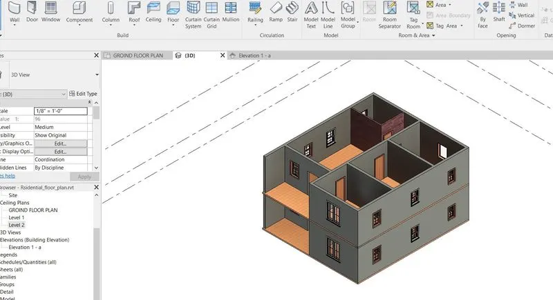
RESULTS
This model of Ground floor Plan align to next floor By using Various tools of Revit Software.
4.AIM
To create a separate rooms within residential unit using the interior partition wall.
INTRODUCTION
- The walls that makes for division or privacy in the interior portion of building and not carried the ceiling load and floor load and that would make with bricks, glass , concrete or other more materials is called partition wall.
PROCEDURE
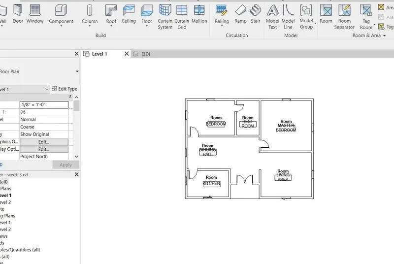
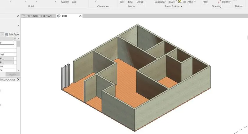
- To create a layout of building plan and then to select the wall that makes to creation of entire floor planning of building.
- After to select the interior wall to create the separate division part of rooms likes bedroom, kitchen, living room, restroom, etc..,.
- To select the thickness of wall @ 4”
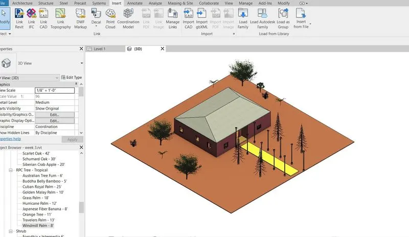
- To create the walkway entry that makes to create a better aesthetic view of surrounding.
RESULTS
The interior partition walls are created successfully.
5.AIM
To create a plan and to insert the components in appropriate locations to add details to the residential building.
INTRODUCTION
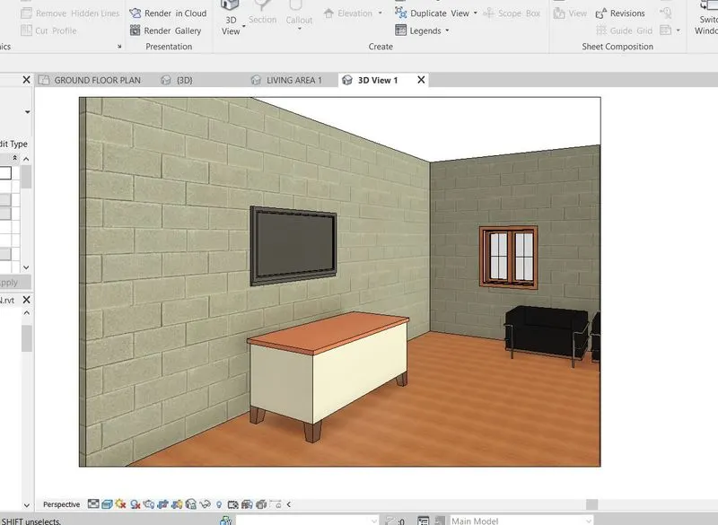
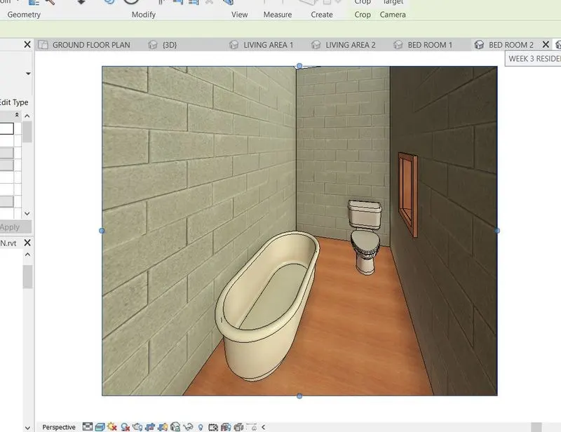
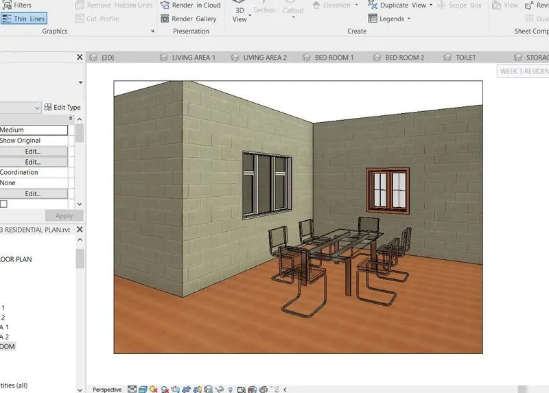
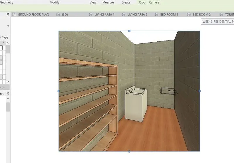
- The residential model components are furniture, couch set, TV desk, shelf cabinets, bed set, self, lighting, individual study desk, bath tub, and plumping fixtures.
PROCEDURE
- To create a plan in appropriate division of plan.
- Then, to select the particular components of their locations like room, hall, kitchen, etc..,
- First we select the hall, go to insert and to choose LOAD Family, for collecting the required components of required place.
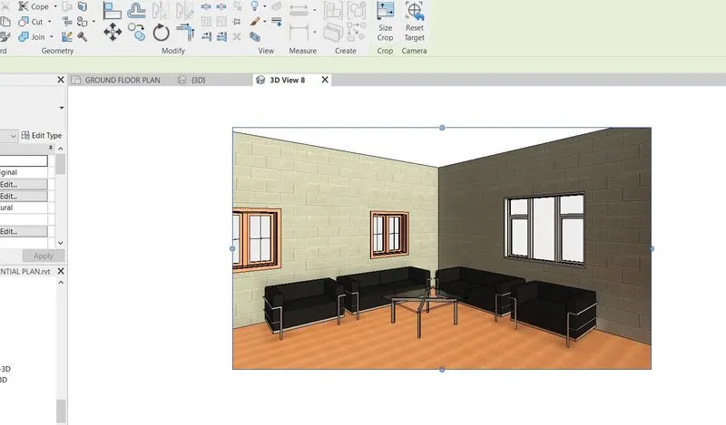
- For hall, to add the furniture of Sofa, Desk, Tea Table, Chair, TV Table, self, etc..,
- For kitchen, to insert the kitchen components from library like Stoves, shelf, sink, wash basin, Dust bin, refrigerator, etc..,
- Next Bed Room, to insert the components of Bed, Sofa, individual study table, lightening, etc..,
- Next toilet, to add the components of Water closets, bath tub.
- Finally, the layout is turned into the view 3D , can visible the all components in building.
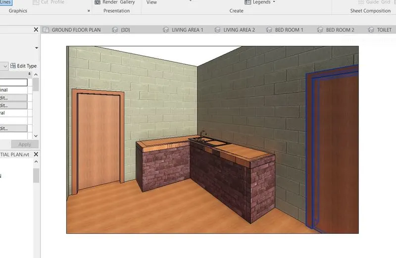
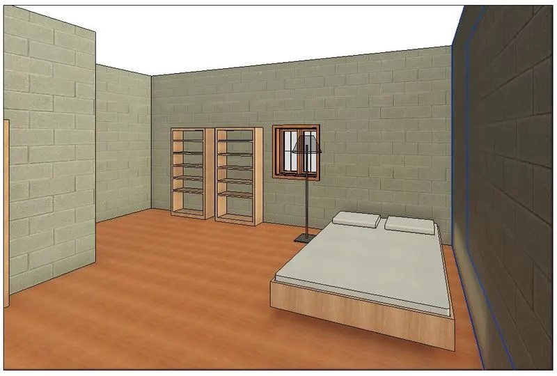
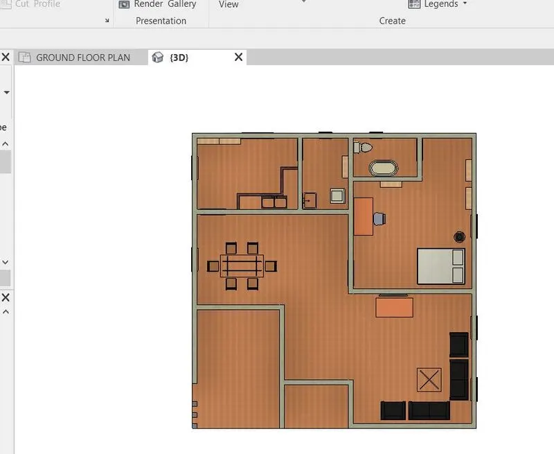
RESULTS
The all components are inserted successfully from the library in the systematic manner.