Creating Walls, Partition walls and Floors for a residential layout using REVIT
1) Use the project file created from Week 2. Use it for this assignment. Based on your layout from week 2, using floor tool under architecture tab and select the floor with appropriate material and thickness using the property browser create a layout in the Ground floor Level. Align the floor plan with grids created from week 2
Ans 1.
INTRODUCTION: Providing Flooring to the Residential Building Layout
AIM: To select the floor finish to ground floor level using floor tool under architectural tab and modifying the material and thickness using the property browser. Creating the grids for the layout.
PROCEDURE:
- Open the previously created Project layout for residential unit and save it as Challenge 3 file
- In ground floor plan, select architectrual tab and then click on floor
- The floor was created using the boundary lines inside the wall inner line.
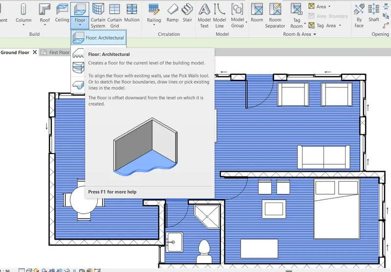
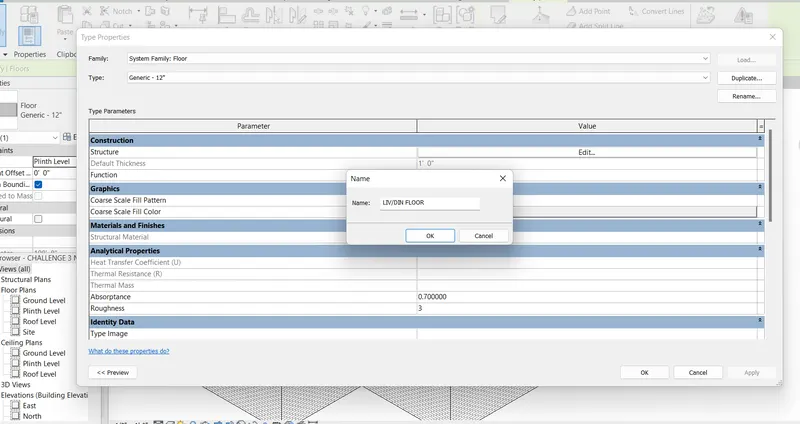
- Select the floor system and duplicate for creating new floor system
- Click on the Edit icon to check the Type properties of floor
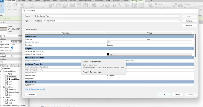
- In the structure click on the edit option to see the layers of the existing floor type
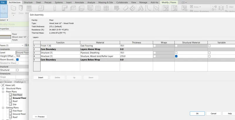
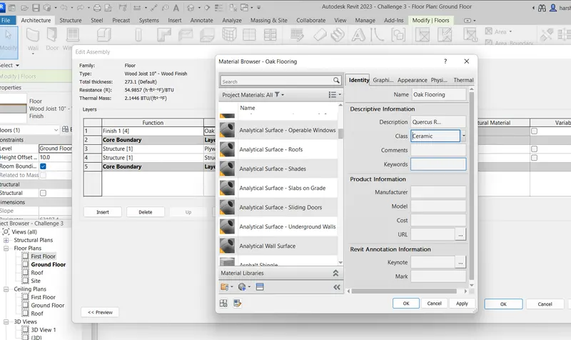
- Click on the floor material to edit the material of floor and properties like pattern and colour.
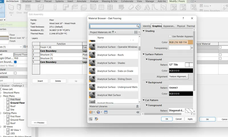
- The properties like Identity, Graphics and Appearance can be modified.
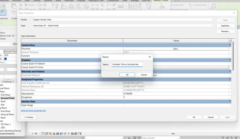
- We have duplicated the flooring type to Porcelain tile on concrete base.
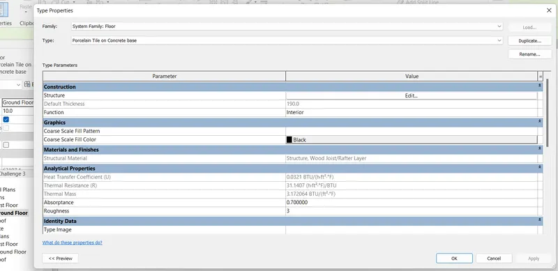
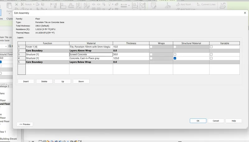
- Click on Edit for the structure of the flooring
- The finish layer is changed to Tile, Porcelain 10mm with 5mm tile glue with total 15mm thickness layer
- The mid layer structure is changed to 50mm Screed concrete
- The bottom base layer is changed to 125mm thick concrete surface
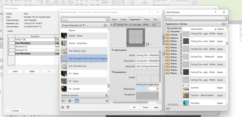
- The finishing for tile can be selected from the Asset browser and applied.
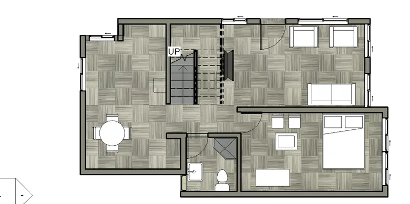
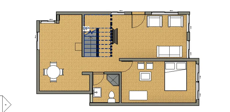
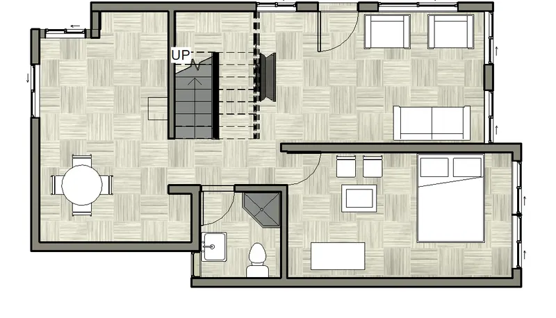
- Few different designs of flooring patterns are shown below.
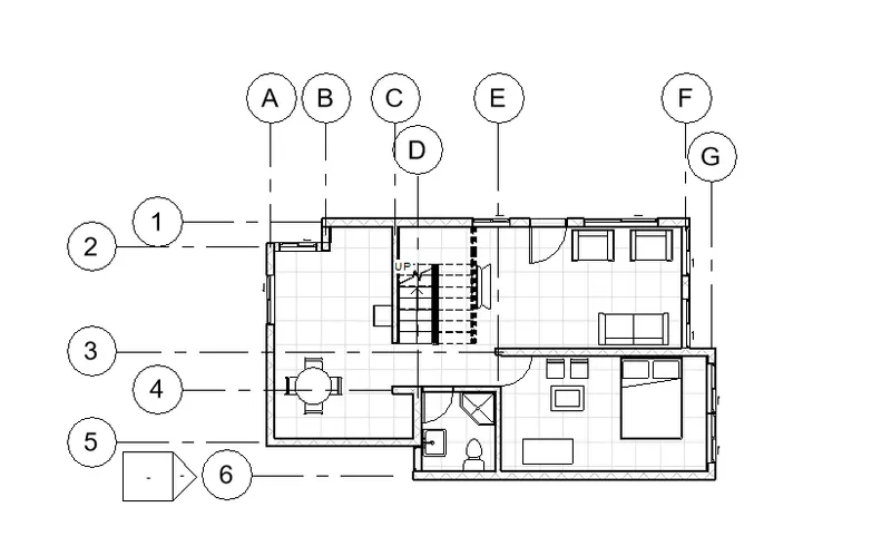
- The grid system is created for the layout wall centers as shown below.
- The configuration of grid lines is from left to right for longitudinal grids and top to bottom for transverse grids.
CONCLUSION: Thus we have selected the floor finish to ground floor level using floor tool under architectural tab and modifying the material and thickness using the property browser. We have also created the grids for the layout.
2) Add walls based on the floor layout. Pick lines or use the draw tool to modify the boundary of walls. Use the property browser to select appropriate material and thickness for walls. After creating the walls verify using the property browser to see if the top and bottom of the walls are constrained.
Ans 2.
INTRODUCTION: Creating walls based on floor layout and checking the properties of wall
AIM: To add the walls based on the floor layout using draw tool to modify the boundary of walls. Selection of the material and thickness of wall using the property browser and verifying the top and bottom wall constraints.
PROCEDURE:
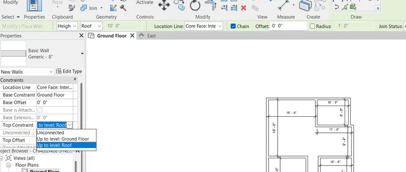
- The walls are provided by clicking on Architectural tab and clicking the architectural wall.
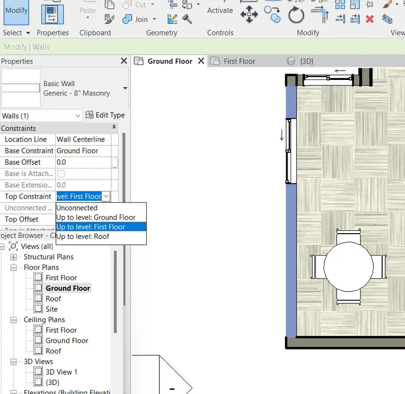
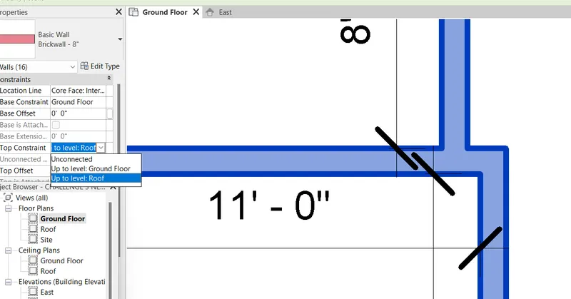
- In the floor plan created the ground floor wall is added to with base constraint as ground floor and top constraint as First floor as shown below
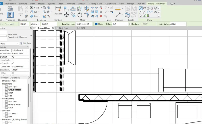
- The external walls selected are 8" thick walls and internal walls are 6" thick walls in the layout.
- To edit the properties of the wall, click on the edit icon in the property browser.
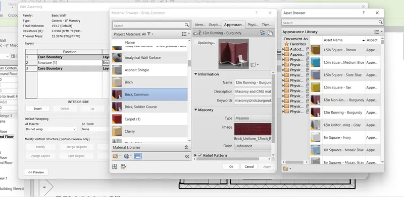
- The Edit assembly window opens with the properties of the wall
- Click on the material to change the material for the wall
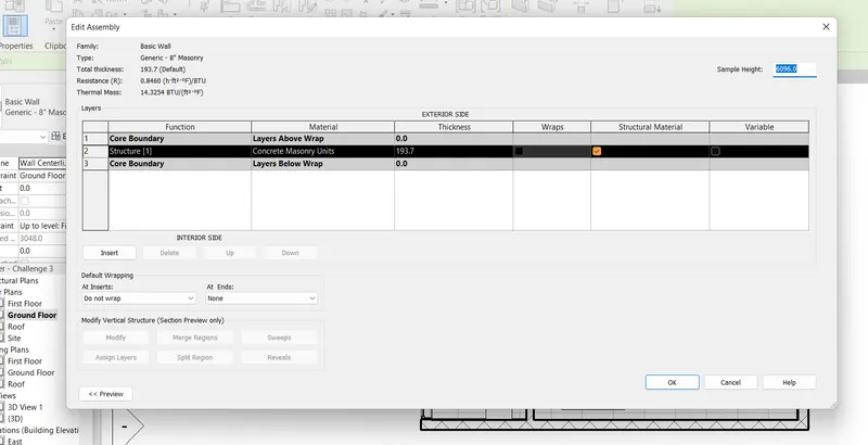
- The material for the wall is changed from the concrete masonry units to common brick assembly and the appearance can be selected from the asset browser.
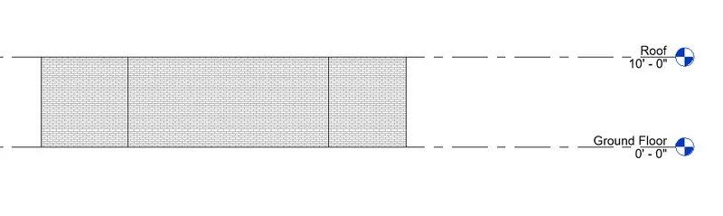
- Wall created using the boundary line in draw tool is shown below
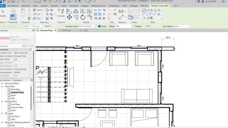
CONCLUSION: Thus we have added the walls based on the floor layout using draw tool to modify the boundary of walls. The material and thickness of wall is done by using the property browser and the top constraint of wall is set to first floor and bottom wall constraint is set to ground floor.
2 a. Based on your observation, what is beneficial for connecting walls with associated levels rather than being Unconnected
Ans 2a. The benefit of connecting walls with the associated levels rather than being unconnected are mentioned below:
- The walls of first floor and ground floor will not be connected so the it will be beneficial if the first floor wall layout is different from the groung floor wall layout.
- The rendering of the first floor wall can be done separately and beneficial if different finishes are intended.
- There is no need to separately specify the height of the wall.
2 b. Which option is convenient for modeling walls, By Height or By Depth?
Ans 2b. Convenient way for modelling walls is by Height as the architectural planning of the building is done ground level to upwards. However if we want to plan basement or structure below the ground the wall modelling by Depth can be done.
3) Copy the model elements ( wall, floor ) modelled to Ground Floor Level and paste it aligned to First Floor Level . Use modify tab to utilize copy and paste options to align
elements to a different level
Ans 3.
INTRODUCTION: Using the copy and paste tabs to copy elements to other place.
AIM: To copy the wall and floor elements modelled to ground floor level and paste it aligned to first floor level by using the modify tab.
PROCEDURE:
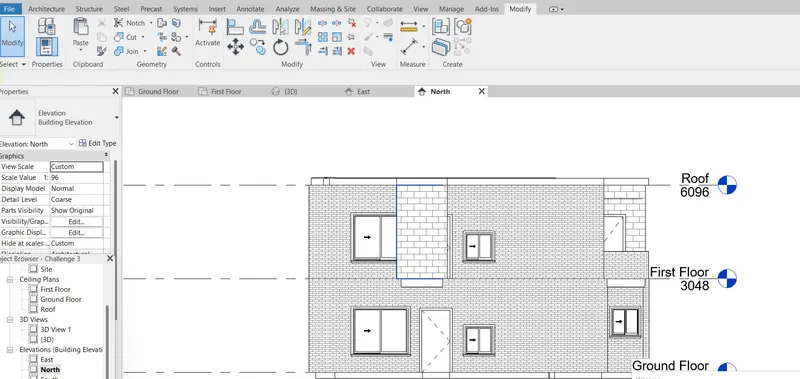
- Select the elevation view.
- Select modify tab
- Copy the required ground floor wall to clipboard
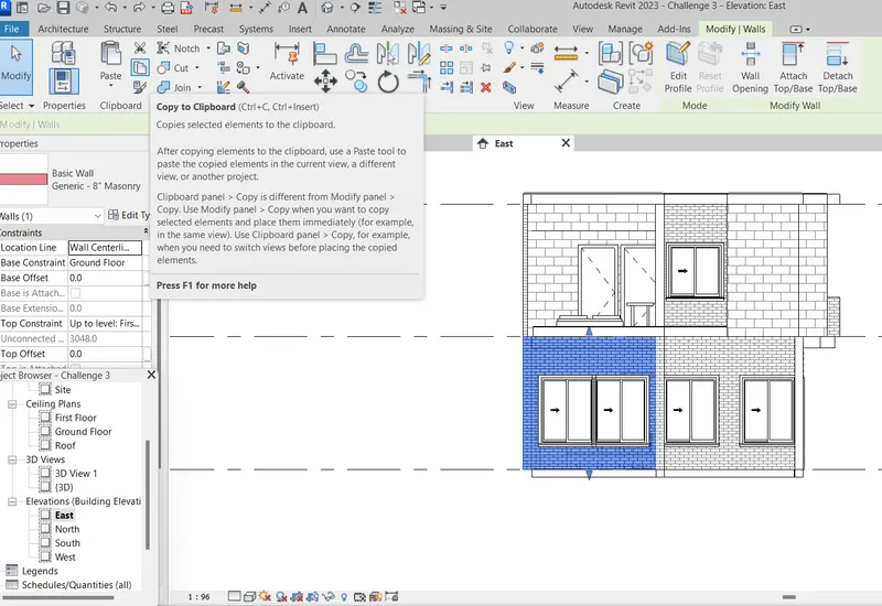
- Paste the wall on upper floor by selecting the point for placing on the first floor.
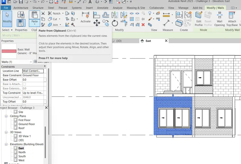
- The wall is pasted on first floor level.
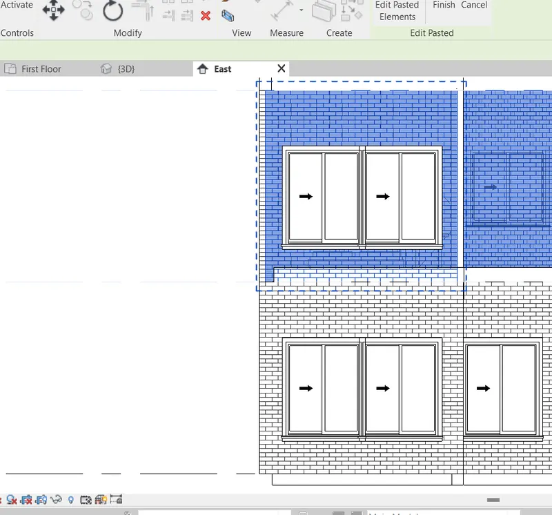
- Alternatively the wall can be pasted by aligning to the selected levels
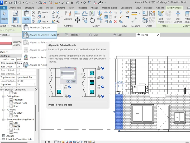
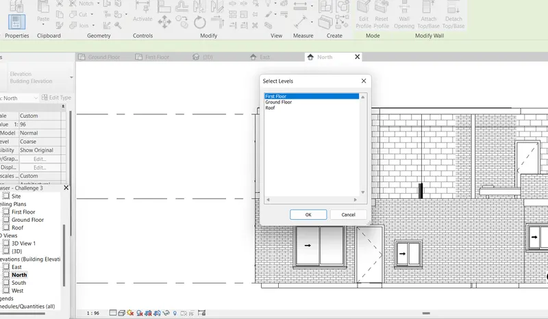
- The select levels window opens and the first floor is selected and the wall is pasted to first floor.
- Window pasted by selecting level is shown below
- The pasting of elements by selecting the levels can be done using floor plan view also.
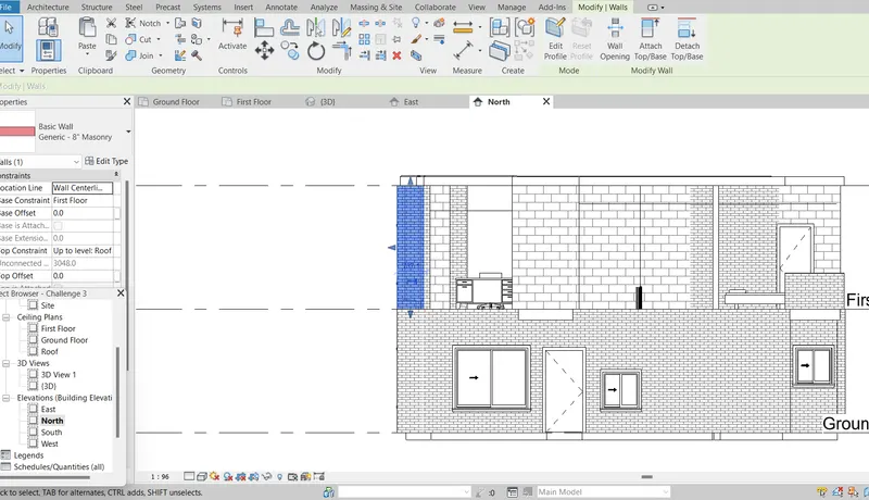
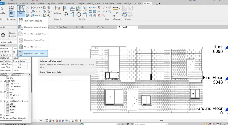
- In the elevation view the elements can be aligned by selecting the picked levels as shown below.
CONCLUSION: Thus we have copied the wall and floor elements modelled to ground floor level and paste it by aligning to first floor level by using the modify tab using various different pasting options from the Clipboard pasting.
4) Use interior partition walls to create separate rooms within your residential unit. The model must include the following rooms
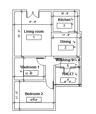
a. Living Room/ Drawing Room ( 15’ X 18’)
b. Dining Room (9’ X 11’)
c. Bed Room ( 9’ X 12’ and 15’ X 11’)
d. Rest Room ( 10’ X 12’ )
e. Kitchen (8’ X 10’)
The above are for examples. You can use them or use your measured entities to create your model based on your layout. You may include entry walkway, Patios or Guest
rooms based on your creativity and purpose of modeling. Convert units if you are using metric system
Ans 4.
INTRODUCTION: Creating the rooms using internal walls boundaries
AIM: To create the rooms using the internal partition walls creating separate rooms.
PROCEDURE:
- Open new Revit file.
- Set the units to Imperial
- Open new project and save it as Challenge 3.4 project
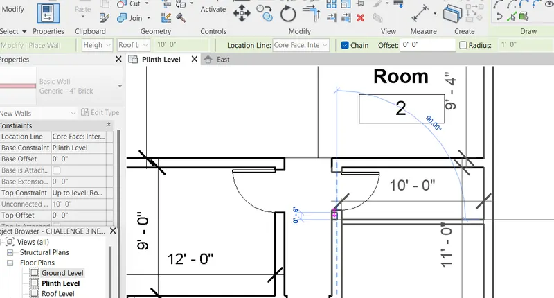
- Draw the building plan using the architectural wall tab
- Edit the properties of the wall as per requirement
- Trim the unwanted walls
- Draw the partition walls inside as per requirement
- Provide the dimensions to the room to check the sizes
- Provide room areas by providing the room boundaries, tags with room name
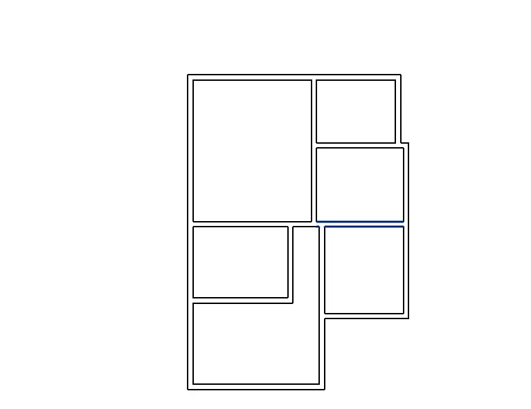
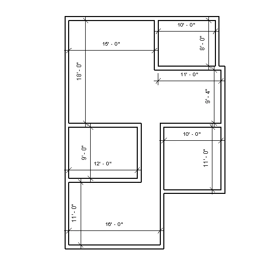
CONCLUSION: Thus we have created the internal walls for residential unit using the internal wall boundaries. The screenshots of the drawing are attached for reference.
5) Based on week 2 assignment, the components to be included in a residential unit were inserted to the Revit file. Place these components in appropriate locations to add details to your residential model
a. Place Doors and windows in the wall at appropriate locations
b. The Living Room must include furniture set, couch table and TV desk and shelf cabinets
c. The Dining Room must include a table and chairs serving the purpose of eating
d. Bed Room must include a bed set, shelf, lighting and individual study desk and chair
e. Rest room should include bath tub and plumbing fixtures discussed in class
f. Kitchen should include countertops, gas stove cabinet and shelves to store food items
g. The wash/storage room can include washing machines and shelves to store clothes
All the components are available in Revit Library. Use them to place at appropriate locations to add details to your model. Use 3D navigation to check the model and its authenticity on a real time basis to verify the model
Ans 5.
INTRODUCTION: Creating various building elements like door, windows and furniture
AIM: To place doors and windows at required room walls at appropriate locations in residential unit layout. Providing the various furniture and equipments in the residential unit layout from the components available in Revit library. Using 3D navigation to check the model and authenticate on real time basis to verify the model.
PROJECT:
- Open the previously created residential layout
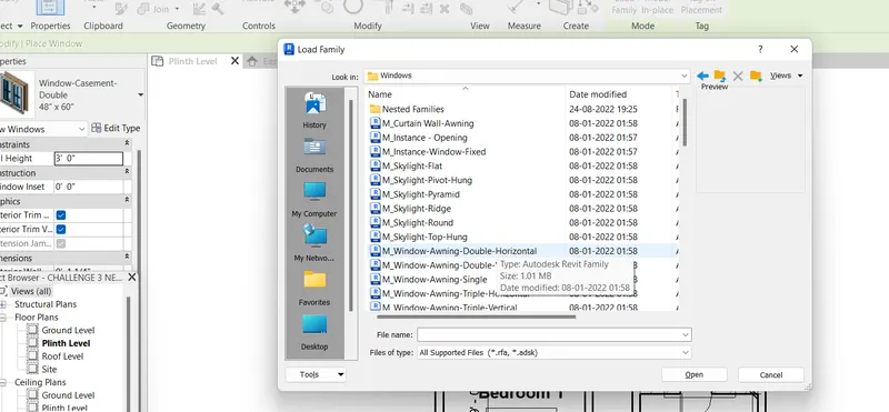
- Provide Architectural doors from the available family or load the family from the Revit Library for the require size and types
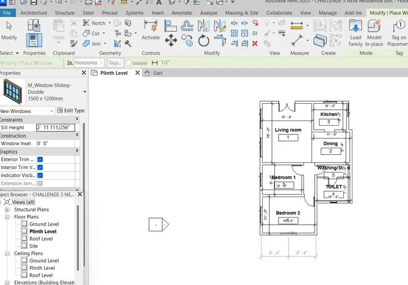
- Provide architectural windows from the window category and family.
- Modify the elements as per the drawing requirement for sizes or finishes.
- Provide the furniture from the funiture catergory and various furniture families
- Provide the equipments from special equipments category for washing machine, fridge etc.
- Using the 3D navigation check the various views for the authenticity of the model on real time basis
- The screenshots of the drawings and 3D views are attached below for reference.
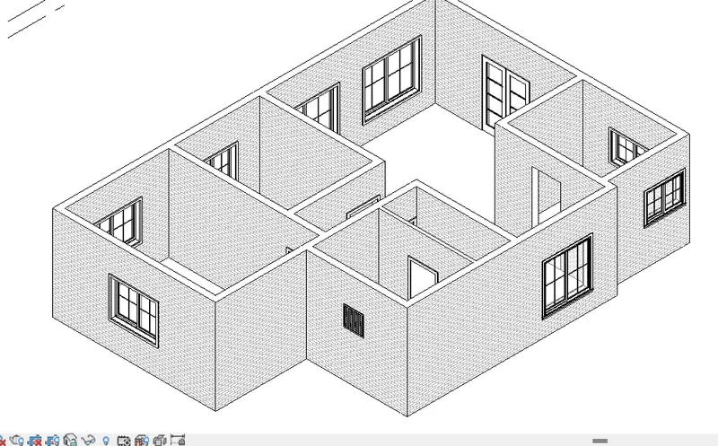
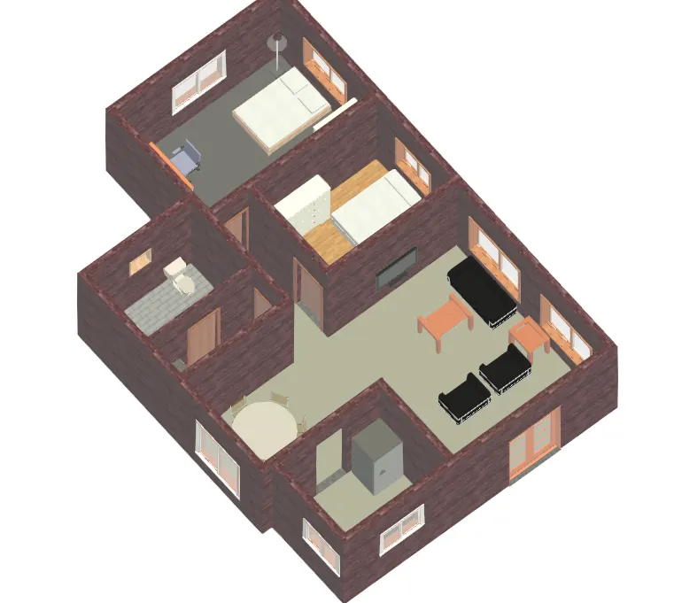
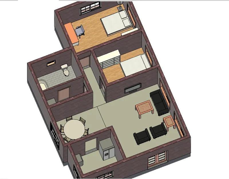
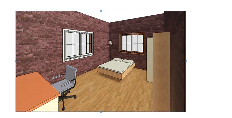
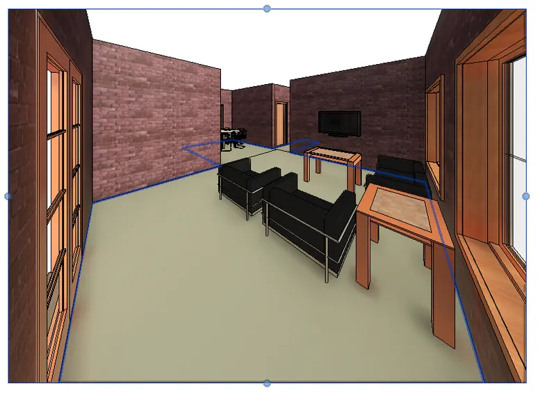
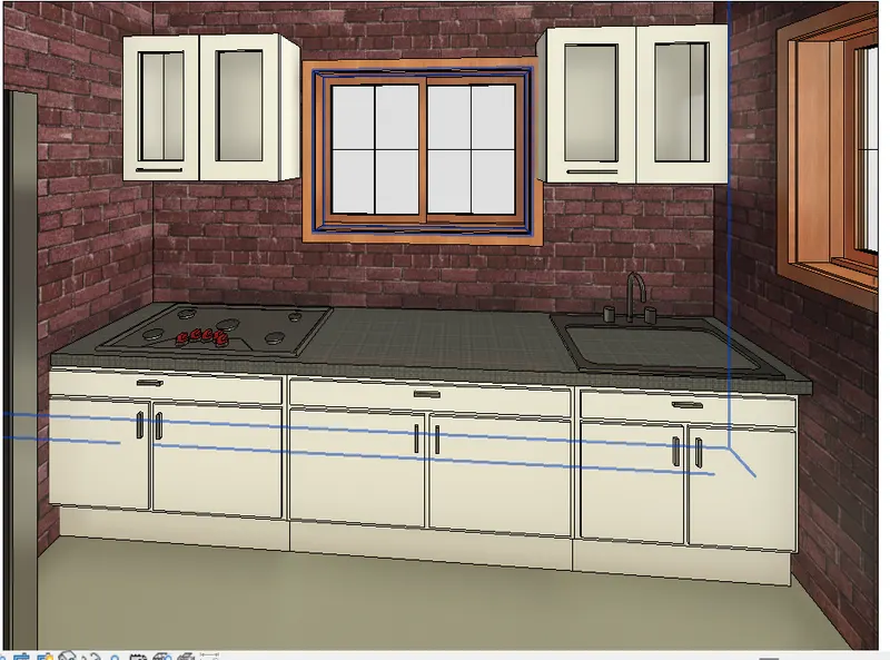
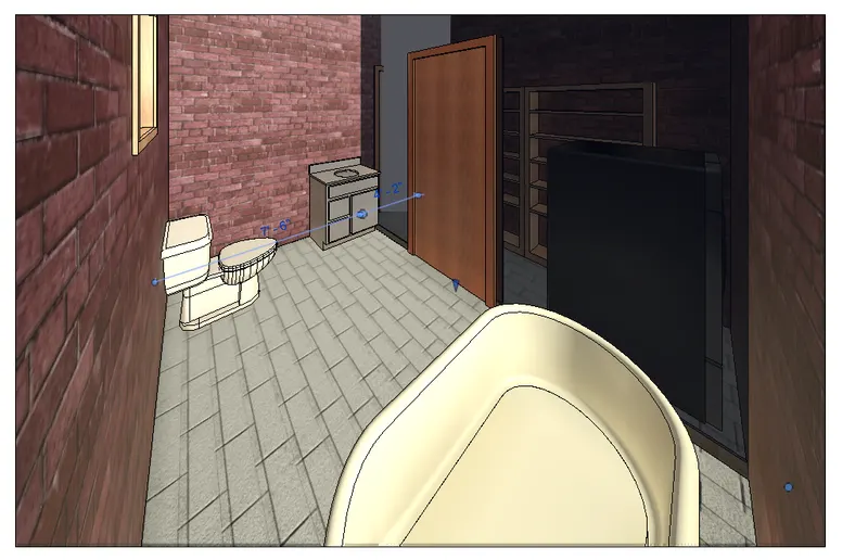
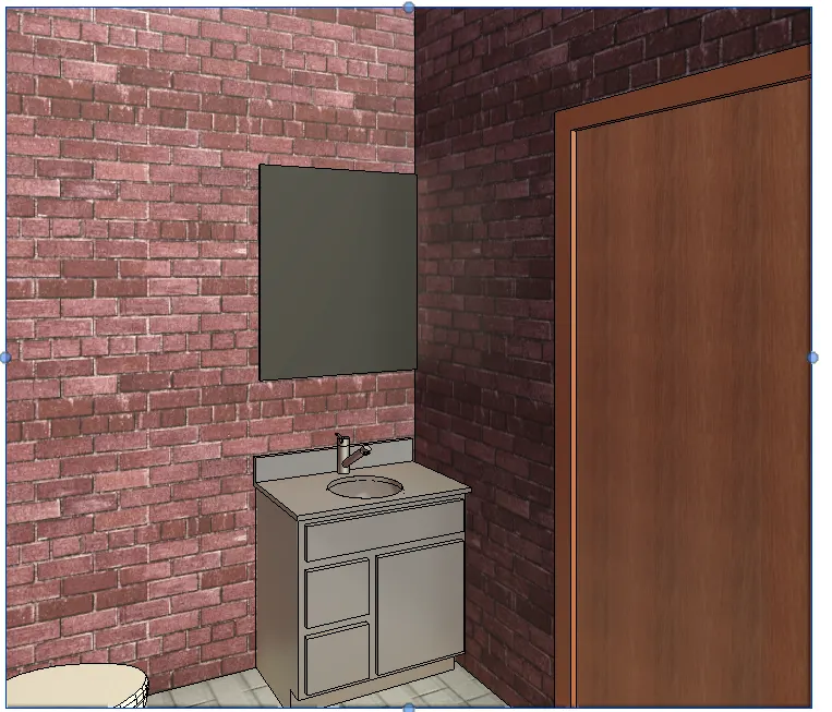
CONCLUSION: Thus we have provided the door, windows, furniture and equipment in the residential building layout and checked the authenticity of the model created on real time basis using the 3D navigation.