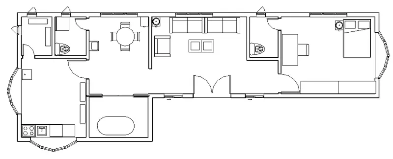
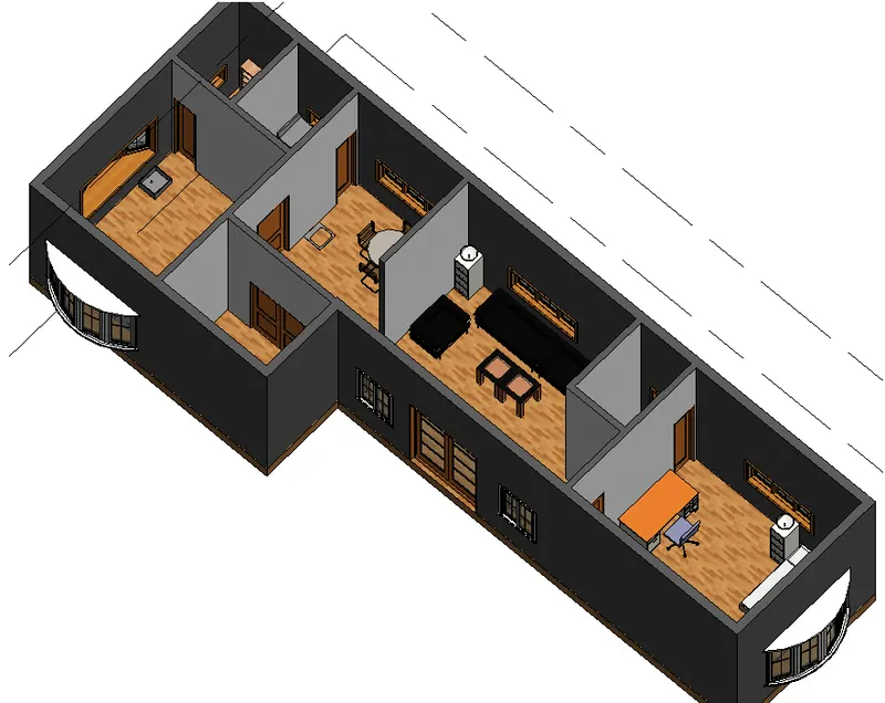
Creating Walls, Partition walls and Floors for a residential layout using REVIT
1) AIM: To create a floor using floor tool under architecture tab and select the floor with appropriate material and thickness using the property browser.
PROCEDURE:
- Go to desktop and select the below shown icon.
- Once the icon the selected then the below shown dialogue box will appear.
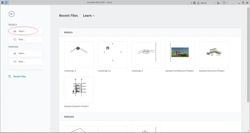
- Here as we have to open a last week challange project file so go to Open option.
- We can also select the drawing by going to models.
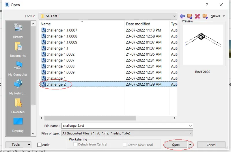
- The above dialogue baox will appear then go to the path where drawing is saved and click open then the drawing will be visible in the drawing sheet.
- Once the drawing is visible in the drawing sheet then go to Architectural box and select the floor option there.

- Once the floor option is selected then a below shown options will appear.
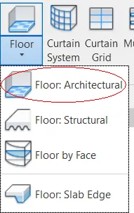
- Here select the architectural floor and a below shown option box will appear.

- Here select the type of Selection to be done in the drawing. Here we are selecting pick line option.
- This will help to select the type of selection to be done and start to do the selection of places where floor has to be done.
- Before selecting the floor the drawing has to be in PLAN view.
- It should be in a level where floor is needed. Then start with the selection.
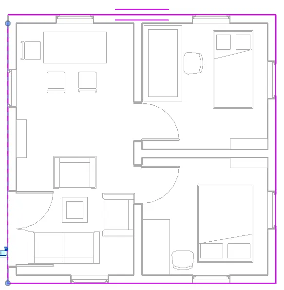
- After selecting the lines or a boundary lines where floor is neede the it will appear as shown above.
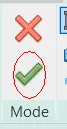
- Then clock the green tick mark and complete the selection if there are any error in the selection a pop up screen will appear.
- After selecting the floor wedges and outer lines the drawing will be visible as shown below.
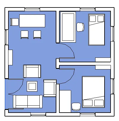
- Once the floor is constructed successfully then we have to add the materials and the thickness.
- Now select the created floor and follow the below steps.
- So to do that we have to go to EDIT TPYE in properties option.
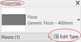
- Once we select the edit type then we will get a dialogue box.
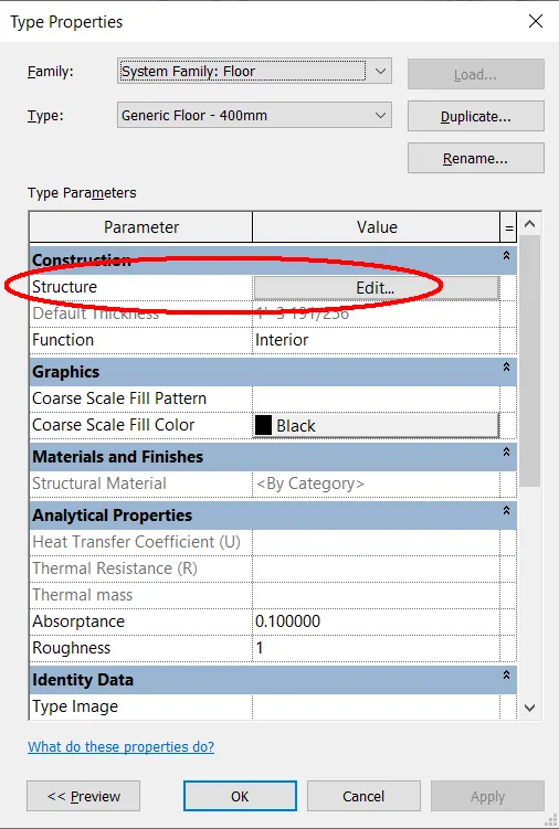
- Here go to structure and select edit this is where we can edit or change the materials.
- Then the below shown dialogue box will appear there we can change the material and thickness both.
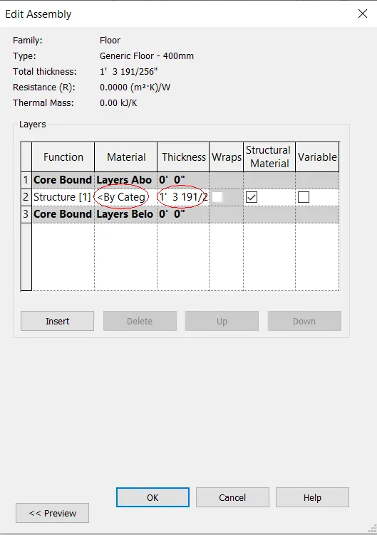
- In material go near structure column and there will be a 3 dot icon select that and a list of different varity materials will come in a dialogue box.

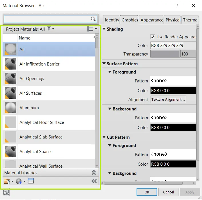
- Here there are n number of materials where we can select the required one.
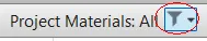
- Select the above shown icon and we can select the material easily by one click.
- Here we are selecting the wood for a trail.
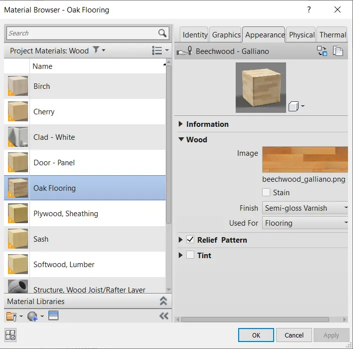
- In wood section we can select the type of material we need and see the appearance of the floor in the right hand side.
- Then click OK then the material will be updated in the EDIT ASSEMBLY dialogue box.
- Then we can change the thickness of the floor as required.
- Then after editing the thickness and material we will be back to TYPE PROPERTIES dialogue box.
- There select apply option and then click OK.
- Then we will be directed to the drawing sheet.
- Then the griding is done as per the procedure from the WEEK 2.
RESULT:
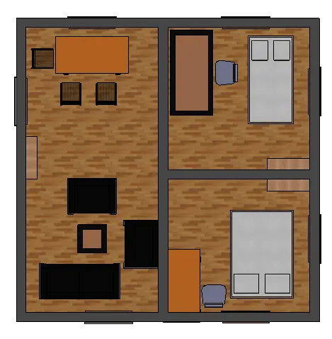
NOTE: The above picture is taken in realistic view for better appearance.
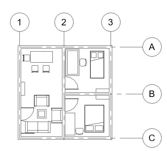
2) AIM: To create a wall based on the floor layout and Use the property browser to select appropriate material and thickness for walls.
PROCEDURE:
- Go to desktop and select the below shown icon.
- Once the icon the selected then the below shown dialogue box will appear.
- Here click NEW option which is present in upper left hand side.
- The above dialogue option will appear.
- Here select the template file and type of project and click OK button.
- Then the drawing sheet will appear with different options to draw and with certain levels.
- Once the drawing sheet is opened now we have to save the drawing.
- Save the drawing using the mentioned steps in previous question.
- Go to architectural toolbar and select wall there are two types of wall.
- Load bearing and Architectural wall select as wanted.
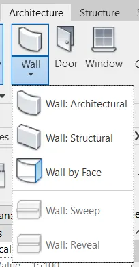
- Select the required type of wall and different options will appear in the toolbar.
- Using those options we can do several editings in wall and different shapes also.

- Here in draw option we can draw the wall in different shapes and size.
- Here we will choose ine option to draw a wall.
- Here we have to select the height of wall.
- Alignment of wall in Location line. Offset if any needed.
- After selecting all the dimensions and doing all the editings now draw the line as required.
- Click anywhere in the drawing sheet and take the curzer horizontally and type 20' the wall will be displayed as shown.
- Now take the cursor in 90degree and type the reading or length as mentioned.
- Carry the same steps and complete the wall in four sides.
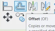
- By this way complete the outer wall and next using offset command draw the interior walls.
- Specify the required room size and do the offset work.
- Keep the wall location line as per requirement. Specify the height as required.
- After completing the constructio of wall now we have to change the material and thickness and edit the respected walls as required.
- So select the first wall which you want to edit and go to edit type in the properties.
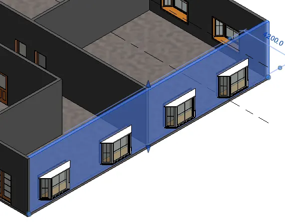
- Go to edit type in properties and a dialogue box will appear
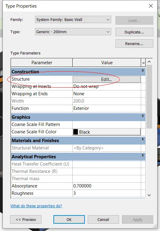
- There go to structure edit and another dialogue box will appear
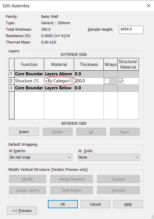
- Here select the three dot icon in the screen and a tab will appear which has varity of wall materials
- There we can also change the size of the wall or thickness of wall as needed
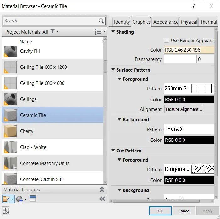
- Select the required material and required shape here we can also seen the preview in the appearance option
- Once you select the material the material is applied to all walls.
- Here this method is used for only particular Object or component.
RESULT:
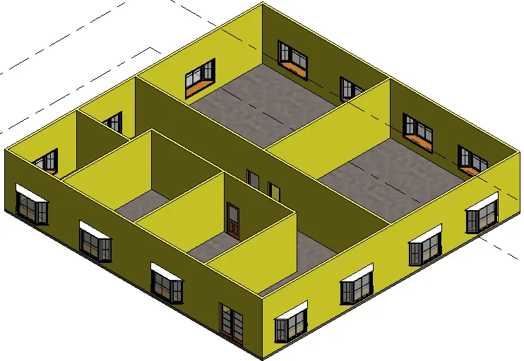
2)b) The more convenient option for modeling walls By height.
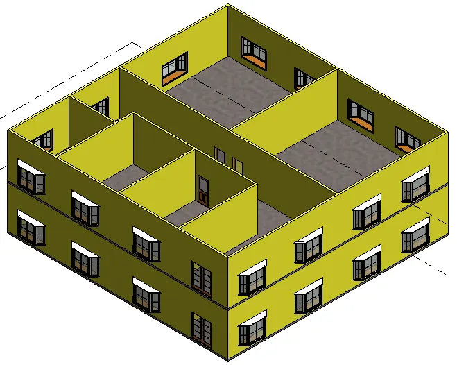
3) AIM: To copy the model elements from Ground Floor Level and paste it aligned to First Floor Level. Using modify tab.
PROCEDURE:
- Go to desktop and select the below shown icon.
- Once the icon the selected then the below shown dialogue box will appear.
- Here click NEW option which is present in upper left hand side.
- The above dialogue option will appear.
- Here select the template file and type of project and click OK button.
- Then the drawing sheet will appear with different options to draw and with certain levels.
- Once the drawing sheet is opened now we have to save the drawing.
- Save the drawing using the mentioned steps in previous question.
- Go to architectural toolbar and select wall there are two types of wall.
- Load bearing and Architectural wall select as wanted.
- Select the required type of wall and different options will appear in the toolbar.
- Using those options we can do several editings in wall and different shapes also.
- Here in draw option we can draw the wall in different shapes and size.
- Here we will choose ine option to draw a wall.
- Here we have to select the height of wall.
- Alignment of wall in Location line. Offset if any needed.
- After selecting all the dimensions and doing all the editings now draw the line as required.
- Click anywhere in the drawing sheet and take the curzer horizontally and type 45' the wall will be displayed as shown.
- Now take the cursor in 90degree and type the reading or length as mentioned.
- Carry the same steps and complete the wall in four sides.
- Once the walls are finished now we have to place the Door, Window and Furnitures using family.
- Then after completing all the aspects of ground floor then we have to copy and paste it for First floor.
- Now select the drawing which has been drawn in ground floor. A new modify tab will appear.
- From that tab select copy to clipboard option.

- Then the drawing will be copyed in the clipboard.
- Now there is paste option beside the copy option select that a new drop menu will come.
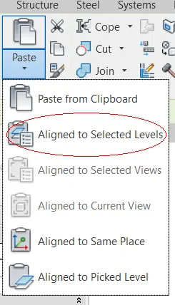
- From there select ALIGNED TO SELECTED LEVELS and again a new tool box will appear.
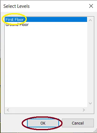
- Here there will be the levels that we have created with the given names.
- Select the required level where we have to copy the drawing.
- Then press ok after selecting the level that we have to copy the drawing.
- We can see the drawing will be copied and pasted in the mentioned level the drawing will be same as that was in ground floor.
- By this way we can copy and paste the drawing from any level to any level.
- We can also use the shortcuts to do this whole process Ctrl+C to copy and Ctrl+V to paste the drawing and the same dialogue box will appear then we have to carry the same steps.
RESULT:
4) AIM: To use interior partition walls to create separate rooms within your residential unit.
PROCEDURE:
- Go to desktop and select the below shown icon.
- Once the icon the selected then the below shown dialogue box will appear.
- Here click NEW option which is present in upper left hand side.
- The above dialogue option will appear.
- Here select the template file and type of project and click OK button.
- Then the drawing sheet will appear with different options to draw and with certain levels.
- Once the drawing sheet is opened now we have to save the drawing.
- Save the drawing using the mentioned steps in previous question.
- Go to architectural toolbar and select wall there are two types of wall.
- Load bearing and Architectural wall select as wanted.
- Select the required type of wall and different options will appear in the toolbar.
- Using those options we can do several editings in wall and different shapes also.
- Here in draw option we can draw the wall in different shapes and size.
- Here we will choose ine option to draw a wall.
- Here we have to select the height of wall.
- Alignment of wall in Location line. Offset if any needed.
- After selecting all the dimensions and doing all the editings now draw the line as required.
- Click anywhere in the drawing sheet and take the curzer horizontally and type 45' the wall will be displayed as shown.
- Now take the cursor in 90degree and type the reading or length as mentioned.
- Carry the same steps and complete the wall in four sides.
- After completing the outer wall then we have to draw the inside partition wall for that we can use either offset command or just draw using line.
- If you need the floor and celling can be done.
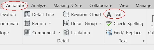
- The text are added using the text option in the Annotate option.
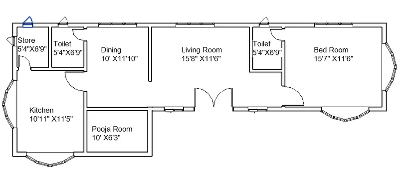
- After naming on room then it is copied and pasted for all other rooms.
RESULT:
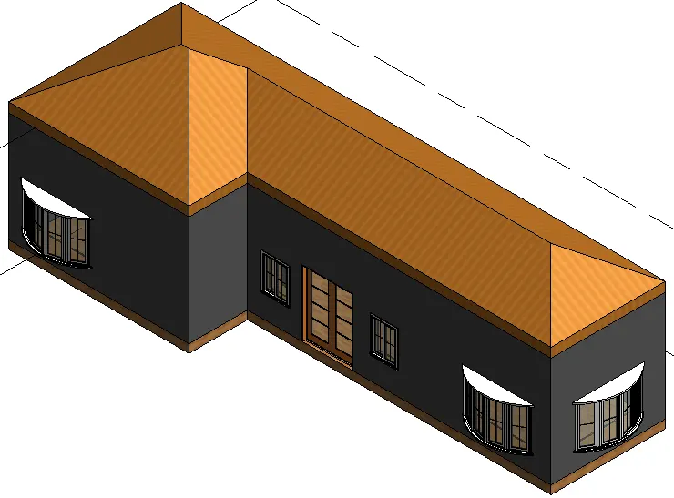
5) AIM: To insert the components that should be included in a residential unit. Place the items for certain rooms as mentioned.
PROCEDURE:
- Go to desktop and select the below shown icon.
- Once the icon the selected then the below shown dialogue box will appear.
- Here click NEW option which is present in upper left hand side.
- The above dialogue option will appear.
- Here select the template file and type of project and click OK button.
- Then the drawing sheet will appear with different options to draw and with certain levels.
- Once the drawing sheet is opened now we have to save the drawing.
- Save the drawing using the mentioned steps in previous question.
- Go to architectural toolbar and select wall there are two types of wall.
- Load bearing and Architectural wall select as wanted.
- Select the required type of wall and different options will appear in the toolbar.
- Using those options we can do several editings in wall and different shapes also.
- Here in draw option we can draw the wall in different shapes and size.
- Here we will choose ine option to draw a wall.
- Here we have to select the height of wall.
- Alignment of wall in Location line. Offset if any needed.
- After selecting all the dimensions and doing all the editings now draw the line as required.
- Click anywhere in the drawing sheet and take the curzer horizontally and type 20' the wall will be displayed as shown.
- Now take the cursor in 90degree and type the reading or length as mentioned.
- Carry the same steps and complete the wall in four sides.
- By this way complete the outer wall and next using offset command draw the interior walls.
- Specify the required room size and do the offset work.
- After completing the drawing now add the family.

- Go to insert and there will be a option as load family there we can add the or there is also another way as shown below.
- Go to door menu and the ribbon tab will change like shown below.

- The above show tab will appear then there select the load family option.
- As soon as we select the load family the below tab will appear.
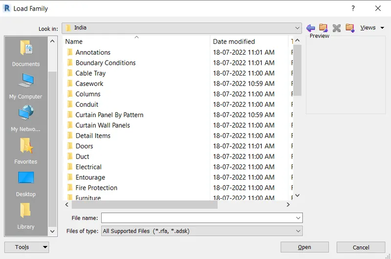
- Here select the target location where the family are located or saved then open the required file and select the required door. The above shown files are called as CATEGORY.
- Once we select the required category then we go to families.
- Here we are going to select the door for the house.
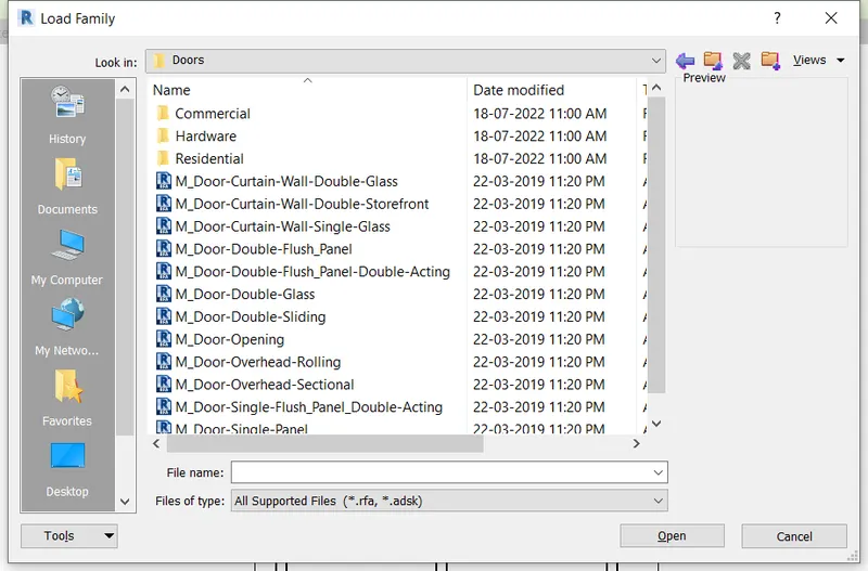
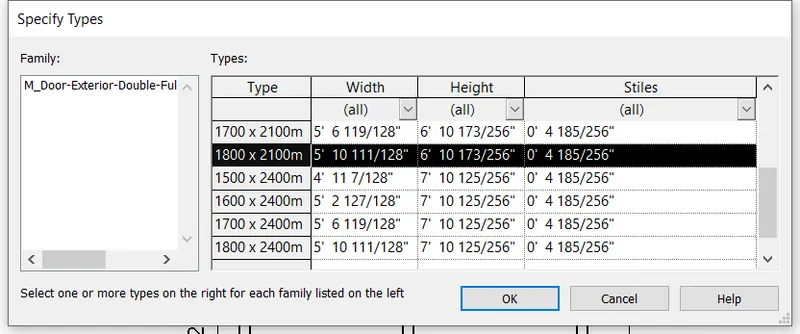
- From the above we will select residential and select the required door and fix it in the wall as per required.
- Same think is done for window and other things.
- For bed, chair etc we have to select the component in the properties bar.
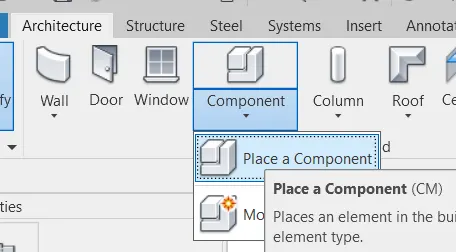
- To place the above mentioned go to component and select place component.
- Follow the same old basic steps and do the designing.
- Then select the design and size as per required and place it where ever required.
- The text are added using the text option in the Annotate option.
- After naming on room then it is copied and pasted for all other rooms.
RESULT: