Creating Walls, Partition walls and Floors for a residential layout using REVIT
1Q]
AIM: -
Draw the Floor to the layout
Assign material to the Floor
Change the thickness properties of the floor.
PROCEDURE: -
Open REVIT software.
Click on open
Open the Challenge_2 Ques-5 File.
Draw the Floor for the walls created.
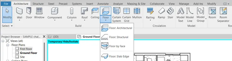
Select Architecture Tab
Go to BUILD panel and chose ARCHITECTURAL FLOOR tool.
Go to DRAW panel
Click on Boundary Line and select the PICK LINES

Pick the lines over the outer walls.
In MODE panel click Tick Mark icon.
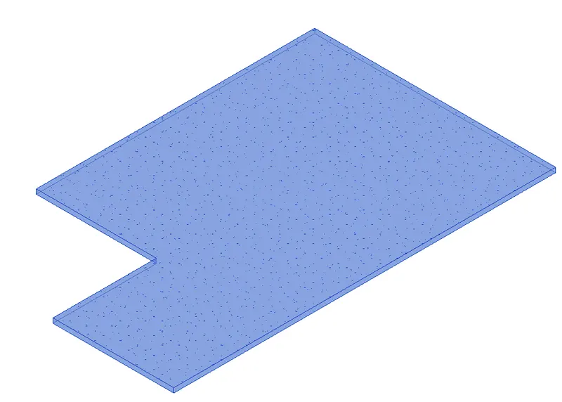
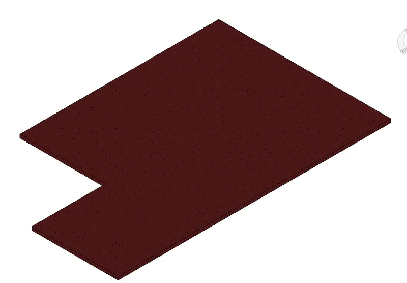
Floor is created.
Change the properties of the FLOOR
Go to PROPERTIES BROWSER
Click on EDIT TYPE
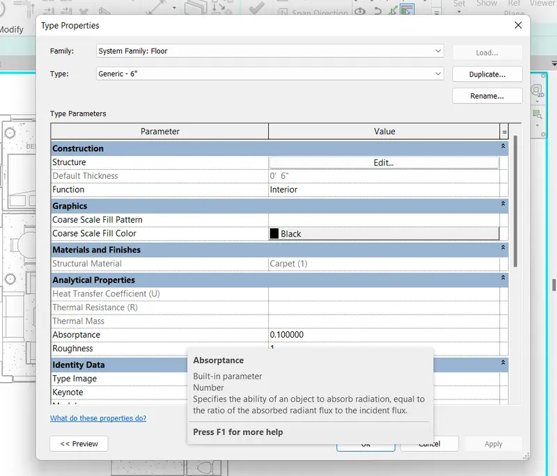
Type Properties dialogue box opens
Click on Duplicate
Change Name: - GENERIC 6”
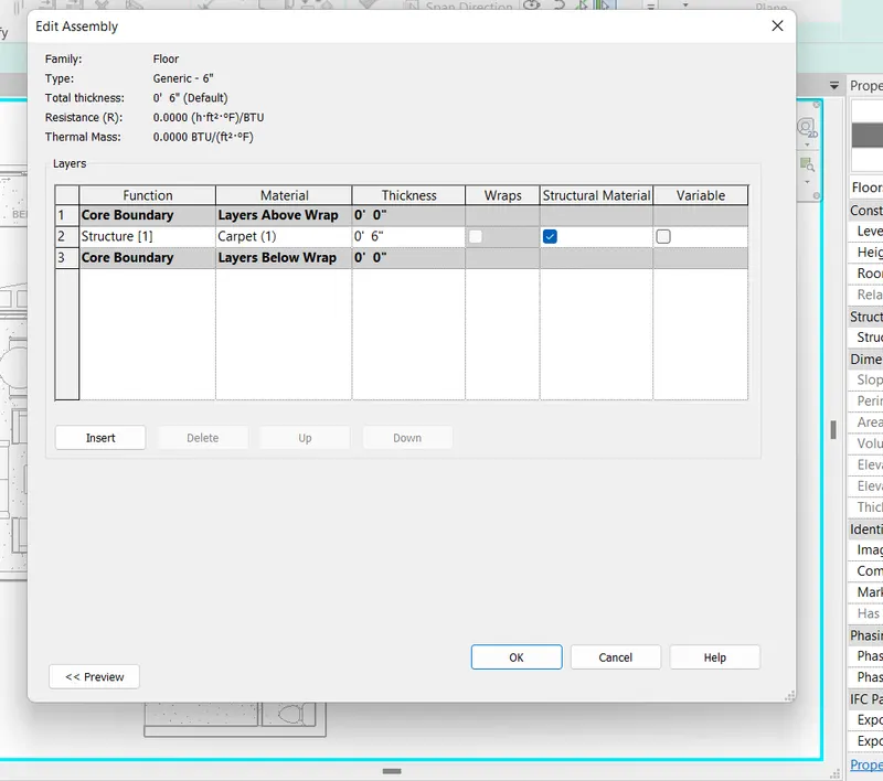
In parameter select STRUCTURE and click on edit
Change the thickness to 6” units.
Under Material click on the 3 dots symbol
Material Browser dialogue box opens
Select the material: Carpet
Press OK.
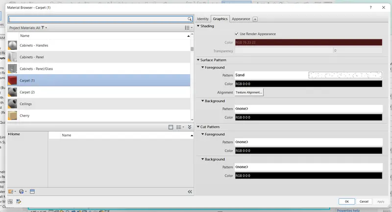
Click Apply in the Type Properties dialogue box.
Selected material is assigned to the Floor.
RESULT: -
We created Floor the layout
We assigned material and changed thickness of the floor in the Properties browser.
2Q]
AIM: -
Draw Walls to the Floor layout
Create Partition walls.
Assign material to the walls
Change thickness of the wall.
Check the constraints of the wall.
PROCEDURE: -
Select ARCHITECTURE Tab
Go to BUILD panel and choose WALL tool.
Choose the LOCATION LINE as per the requirement from the list.
Go to DRAW panel
select the PICK LINES
Pick the outer lines of the Floor
Draw OUTER WALLS
Go to PROPERTIES BROWSER
Change the properties of the wall
Click on EDIT TYPE
Type Properties dialogue box opens
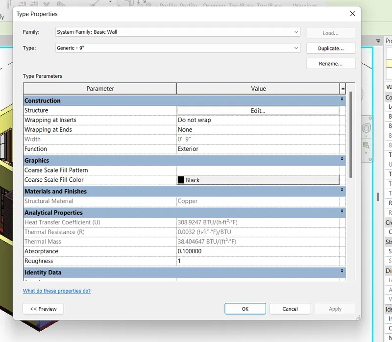
Click on Duplicate
Change Name: - GENERIC 9”
Select parameter STRUCTURE and click on edit
Change the thickness to 9” units.
Press OK.
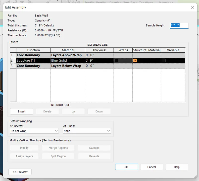
Under Material click on the 3 dots symbol
Material Browser dialogue box opens
Select the material: Blue,solid
Press OK.
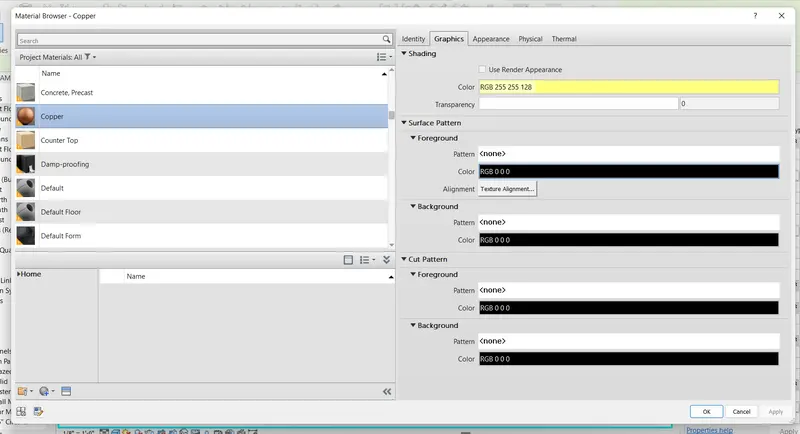
Click Apply in the Type Properties dialogue box.
Selected material is assigned to the Floor.
Select ARCHITECTURE Tab
Go to BUILD panel and choose WALL tool.
Choose the LOCATION LINE as per the requirement from the list.
Go to DRAW panel
select the LINE

Go to PROPERTIES BROWSER
Change the properties of the wall
Select GENERIC BASIC- 4” BRICK
Draw the Partition Walls.
Go to PROPERTIES BROWSER
Under Material click on the 3 dots symbol
Material Browser dialogue box opens
Select the material: BRICK SOLDIER COURSE
Press OK.
Change the Colour in the APPEARANCE TAB
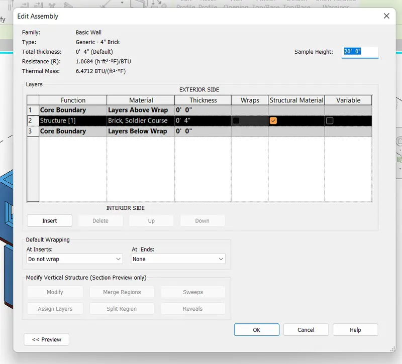
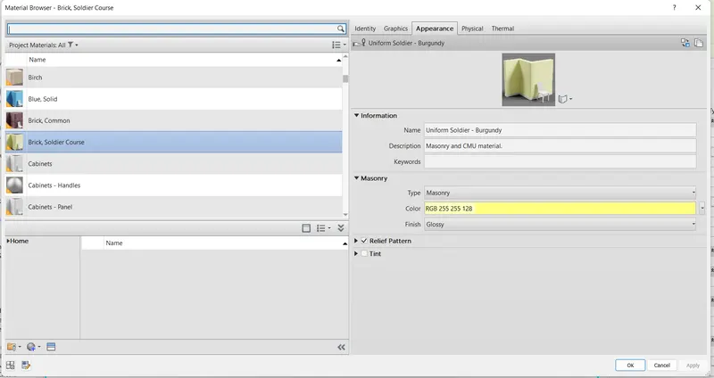
PRESS ok and Apply the changes to the wall.
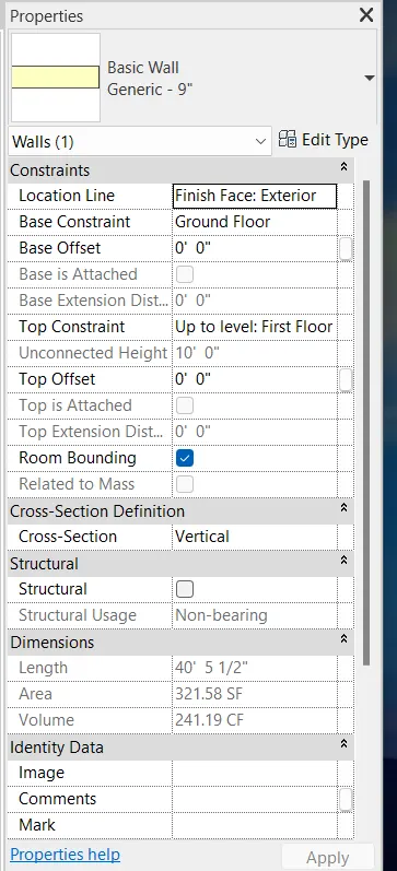
Select the WALLS
Go to PROPERTIES BROWSER
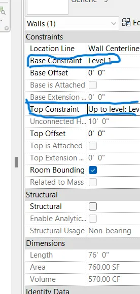
Set the BASE CONSTRAINT: LEVEL 1
Set the TOP CONSTRAINT: LEVEL 2
Press APPLY
Press OK
RESULT: -
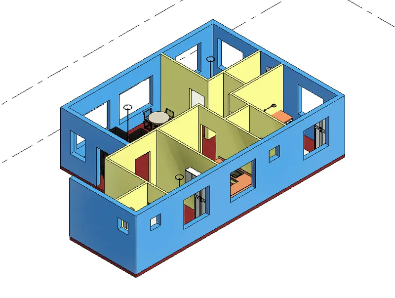
We created Walls to the Floor layout
Created Partition walls.
Assigned material to the walls.
Changed thickness of the wall as per the wall
Checked the Top and Bottom constraints of the wall.
a]
By connecting WALLS with the associated levels we can change the elevation height easily just by changing the value of the respective LEVELS.
Editing the Wall height and floor height is at ease.
Attaching the Floor to the walls is easy by connecting walls with the associated Levels.
b]
Modelling the walls by Height option is convenient.
We can draw the walls from Zero Level to Top Level
No confusion while creating Floors levels.
3Q]
AIM: -
Copy the model elements (wall, floor) modelled to Ground Floor Level
Paste it aligned to First Floor Level.
PROCEDURE: -
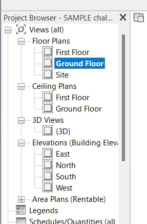
In the Project Browser, Go to Floor Plans
Select Ground Floor
Select the complete model.
Modify tab opens
Select COPY TO CLIPBOARD

After selecting the model, PASTE tool activates
Click on the PASTE and select ALIGNED TO SELECTED LEVELS

Select levels box opens.
Select the required level to align: First Floor.
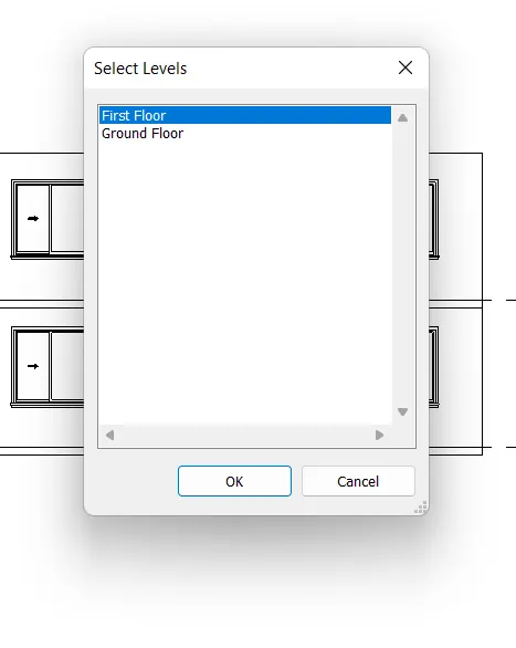
Model aligns perfectly to the First Floor.
Go to BUILD panel and chose ARCHITECTURAL FLOOR tool.
Go to DRAW panel
Click on Boundary Line and select the Rectanagle
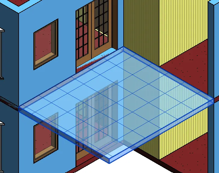
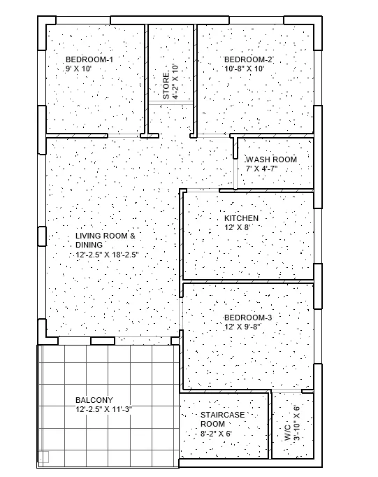
Draw Rectangle for the Balcony at the Entrance
In MODE panel click Tick Mark icon.
Floor for balcony is created.
Change the properties of the FLOOR
Go to PROPERTIES BROWSER
Click on EDIT TYPE
Type Properties dialogue box opens
Click on Duplicate
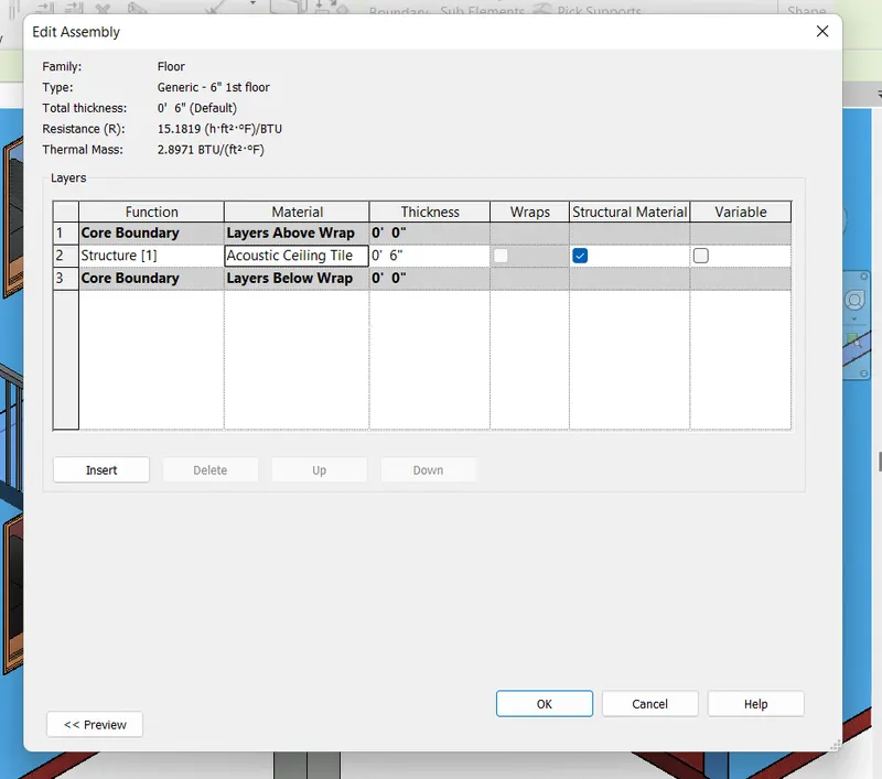
Change Name: - GENERIC 6" 1st floor
In parameter select STRUCTURE and click on edit
Change the thickness to 6” units.
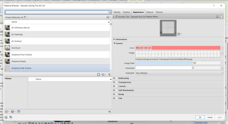
Under Material click on the 3 dots symbol
Material Browser dialogue box opens
Select the material: Acoustic ceiling Tile
Press OK.
Click Apply in the Type Properties dialogue box.
Selected material is assigned to the Floor.
Select ARCHITECTURE Tab
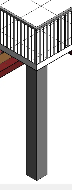
Go to BUILD panel and choose COLUMN tool.
Select the Architectural column from the dropdown list
Place the column at the required position.
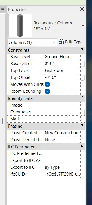
Click on the column and go to Properties browser.
Here change the required data.
Click on EDIT TYPE
Change the dimensions of column to 1’ x 1’
Click Apply ad then OK
Change the other parameters
Base Level: Ground Floor
Base offset
Top level: First Floor
Top offset: -6”
Click Apply.
Select ARCHITECTURE Tab
Go to CIRCULATION panel and choose RAILING tool.
Select Sketch path option from the dropdown list.
Go to DRAW panel
Click on Boundary Line and select the PICK LINES
Pick the lines over the outer Floor at the required position
In MODE panel click Tick Mark icon.
Railing is created.
Click on RAILING in model space.
Go to PROPETIES BROWSER
Change the base level to: First Floor.
Click Apply and Then OK.
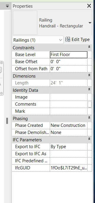
RESULT: -
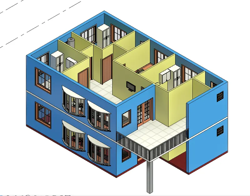
Using MODIFY TAB we copied the model elements (wall, floor) modelled to Ground Floor Level, pasted and aligned to First Floor Level.
We created Balcony to the First Floor.
We Created Floor To the balcony and assigned material to it.
We Created Railing to the Balcony in the First Floor
We Created Column support to the balcony in the Ground Floor.
4Q]
AIM: -
Draw Partition walls.
Create separate rooms using Partition walls.
Living & Dining- 12’-2” x 18’-2”
Bedroom 1- 9’ x 10’
Washroom- 4’-2” x 10’
Bedroom 2- 10’-8” x 10’
Store- 8’ x 4’-8”
Kitchen- 12’ x 8’
Guestroom (Bedroom 3)- 12’ x 9’-8”
Washroom 2 – 3’-10” x 6’
Staircase room- 8’-2” x 6’
Entrance porch- 12’-2” x 11’-3”
Assign material to all walls.
create Room Tags
PROCEDURE: -
Select ARCHITECTURE Tab
Go to BUILD panel and choose WALL tool.
Choose the LOCATION LINE as per the requirement: Finish Face Exterior
Change the properties of the wall
Go to PROPERTIES BROWSER
Click on EDIT TYPE
Type Properties dialogue box opens
Click on Duplicate
Change Name: - GENERIC 9”
Select parameter STRUCTURE and click on edit
Change the thickness to 9” units.
Press OK.
Under Material click on the 3 dots symbol
Material Browser dialogue box opens
Select the material: Blue, solid
Go to PROPERTIES BROWSER
Set the BASE CONSTRAINT: LEVEL 1
Set the TOP CONSTRAINT: LEVEL 2
Press APPLY
Press OK
Go to DRAW panel
Select the PICK LINES
Pick the lines on the Floor layout
In MODE panel click Tick Mark icon.
Outer walls are created.
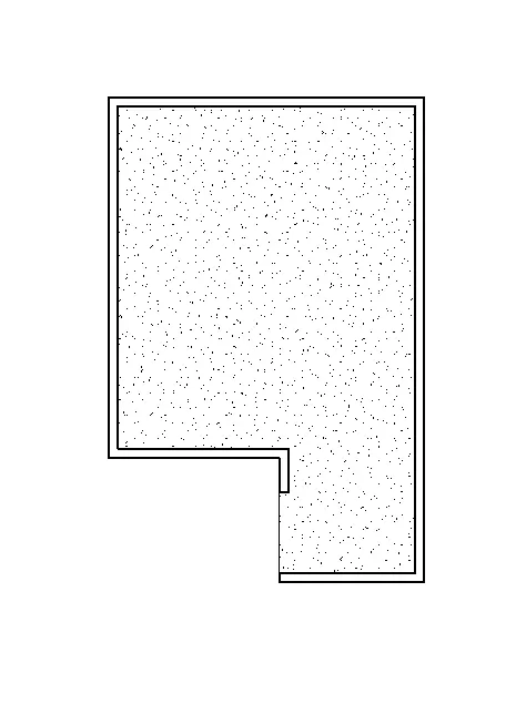
Select ARCHITECTURE Tab
Go to BUILD panel and choose WALL tool.
Choose the LOCATION LINE as per the requirement: Finish Face Exterior
In MODIFY TAB, Go to Modify panel
Select OFFSET tool
Specify Offset distance: 9’ units.
Go to PROPERTIES BROWSER
Select GENERIC BASIC- 4” BRICK
Click on EDIT TYPE
Type Properties dialogue box opens
Under Material click on the 3 dots symbol
Material Browser dialogue box opens
Select the material: BRICK SOLDIER COURSE
Press OK.
Change the Colour in the APPEARANCE TAB
PRESS ok and Apply the changes to the wall
Set the BASE CONSTRAINT: LEVEL 1
Set the TOP CONSTRAINT: LEVEL 2
Press APPLY
Press OK
Click on GENERIC BASIC- 4” BRICK
Dimensions appear on the model space
Click on the dots of the dimension leg and set the dots to inner dimensions.
Edit the inner distance to 9’ units.
Type WA
Select the outer wall
Select OFFSET tool
Specify Offset distance: 10’ units.
Go to PROPERTIES BROWSER
Select GENERIC BASIC- 4” BRICK
Wall type changes to Partition wall
Click on GENERIC BASIC- 4” BRICK
Dimensions appear on the model space
Click on the dots of the dimension leg and set the dots to inner dimensions.
Edit the inner distance to 10’ units.
Room 1 is created.
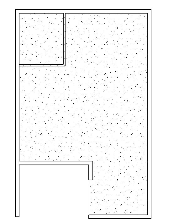
Type WA
Select partition wall
Select OFFSET tool
Specify Offset distance: 4'-2" units.
Click on GENERIC BASIC- 4” BRICK
Dimensions appear on the model space
Click on the dots of the dimension leg and set the dots to inner dimensions.
Edit the inner distance to 4'-2" units.
Press Enter
Type WA
Select partition wall
Select OFFSET tool
Specify Offset distance: 7' units.
Click on GENERIC BASIC- 4” BRICK
Dimensions appear on the model space
Click on the dots of the dimension leg and set the dots to inner dimensions.
Edit the inner distance to 7' units.
Press Enter
Room 2 is created.
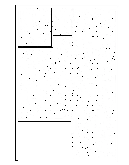
Type WA
Select partition wall
Select OFFSET tool
Specify Offset distance: 10'-8" units.
Click on GENERIC BASIC- 4” BRICK
Dimensions appear on the model space
Click on the dots of the dimension leg and set the dots to inner dimensions.
Edit the inner distance to 10'-8" units.
Press Enter
Type WA
Select partition wall
Select OFFSET tool
Specify Offset distance: 10' units.
Click on GENERIC BASIC- 4” BRICK
Dimensions appear on the model space
Click on the dots of the dimension leg and set the dots to inner dimensions.
Edit the inner distance to 10' units.
Press Enter
Room 3 is created.
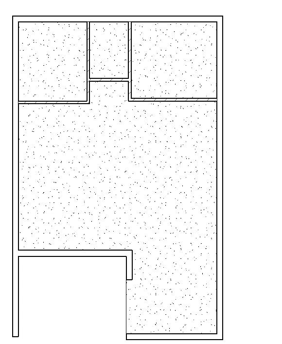
Type WA
Select partition wall
Select OFFSET tool
Specify Offset distance: 7' units.
Click on GENERIC BASIC- 4” BRICK
Dimensions appear on the model space
Click on the dots of the dimension leg and set the dots to inner dimensions.
Edit the inner distance to 7' units.
Press Enter
Type WA
Select partition wall
Select OFFSET tool
Specify Offset distance: 4'-8"units.
Click on GENERIC BASIC- 4” BRICK
Dimensions appear on the model space
Click on the dots of the dimension leg and set the dots to inner dimensions.
Edit the inner distance to 4'-8" units.
Press Enter
Room 4 is created.
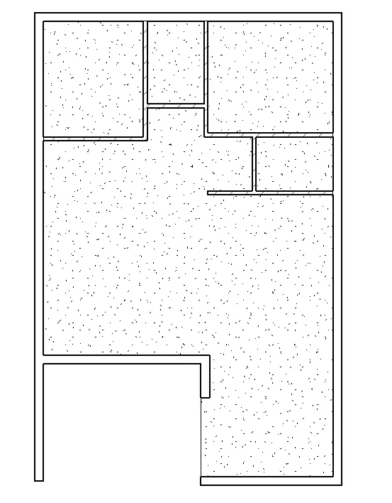
Type WA
Select partition wall
Select OFFSET tool
Specify Offset distance: 12' units.
Click on GENERIC BASIC- 4” BRICK
Dimensions appear on the model space
Click on the dots of the dimension leg and set the dots to inner dimensions.
Edit the inner distance to 12' units.
Press Enter
Type WA
Select partition wall
Select OFFSET tool
Specify Offset distance: 8' units.
Click on GENERIC BASIC- 4” BRICK
Dimensions appear on the model space
Click on the dots of the dimension leg and set the dots to inner dimensions.
Edit the inner distance to 8' units.
Press Enter
Room 5 is created.
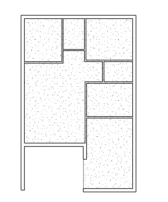
Type WA
Select partition wall
Select OFFSET tool
Specify Offset distance: 12' units.
Click on GENERIC BASIC- 4” BRICK
Dimensions appear on the model space
Click on the dots of the dimension leg and set the dots to inner dimensions.
Edit the inner distance to 12' units.
Press Enter
Type WA
Select partition wall
Select OFFSET tool
Specify Offset distance: 9'-8" units.
Click on GENERIC BASIC- 4” BRICK
Dimensions appear on the model space
Click on the dots of the dimension leg and set the dots to inner dimensions.
Edit the inner distance to 9'-8" units.
Press Enter
Room 6 is created.
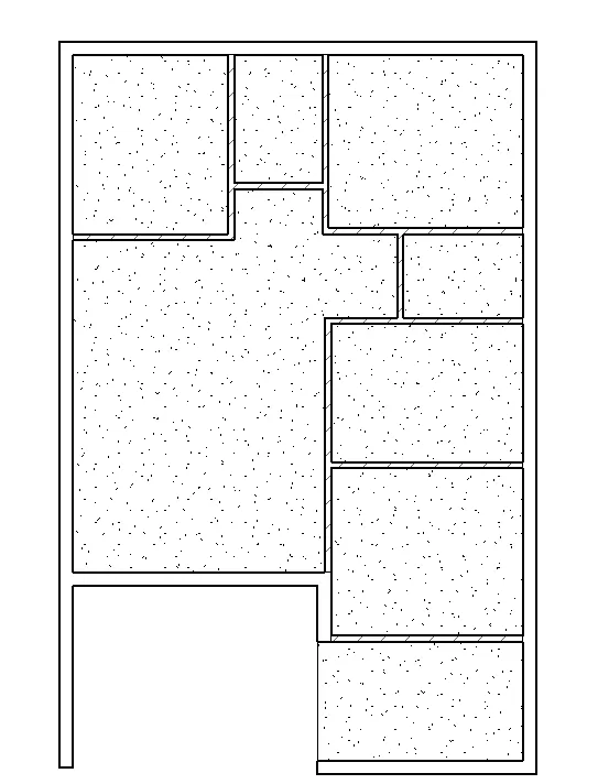
Type WA
Select the outer wall
Select OFFSET tool
Specify Offset distance: 3'-10" units.
Go to PROPERTIES BROWSER
Select GENERIC BASIC- 4” BRICK
Wall type changes to Partition wall
Click on GENERIC BASIC- 4” BRICK
Dimensions appear on the model space
Click on the dots of the dimension leg and set the dots to inner dimensions.
Edit the inner distance to 3'-10" units
Press Enter
Room 7 is created.
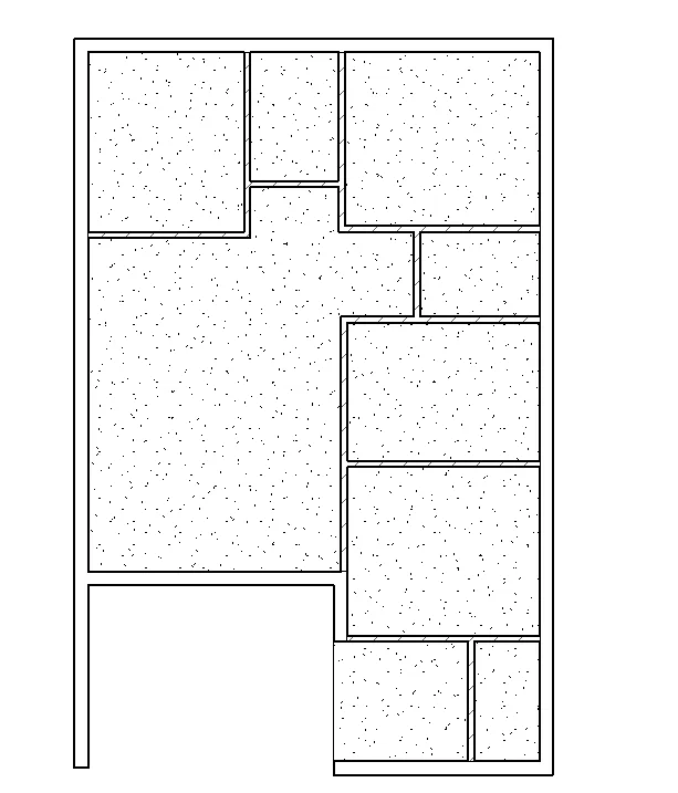
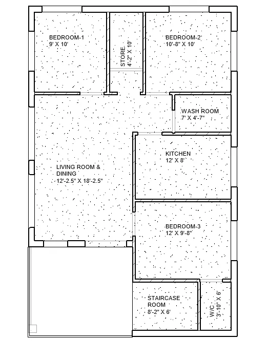
Separate rooms are created.
In the Project Browser, Go to Floor Plans
Select Ground Floor
Select the complete model.
Modify tab opens
Select COPY TO CLIPBOARD
After selecting the model, PASTE tool activates
Click on the PASTE and select ALIGNED TO SELECTED LEVELS
Select levels box opens.
Select the required level to align: First Floor.
Model aligns perfectly to the First Floor.
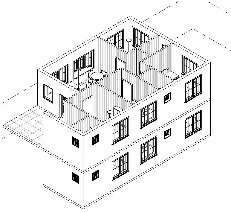
Select ARCHITECTURE Tab
Go to BUILD panel and choose COLUMN tool.
Select the Architectural column from the dropdown list
Place the column at the required position.
Click on the column and go to Properties browser.
Here change the required data.
Click on EDIT TYPE
Change the dimensions of column to 1’ x 1’
Click Apply ad then OK
Change the other parameters
Base Level: Ground Floor
Base offset
Top level: First Floor
Top offset: -6”
Click Apply.
Select ARCHITECTURE Tab
Go to CIRCULATION panel and choose RAILING tool.
Select Sketch path option from the dropdown list.
Go to DRAW panel
Click on Boundary Line and select the PICK LINES
Pick the lines over the outer Floor at the required position
In MODE panel click Tick Mark icon.
Railing is created.
Click on RAILING in model space.
Go to PROPETIES BROWSER
Change the base level to: First Floor.
Click Apply and Then OK.
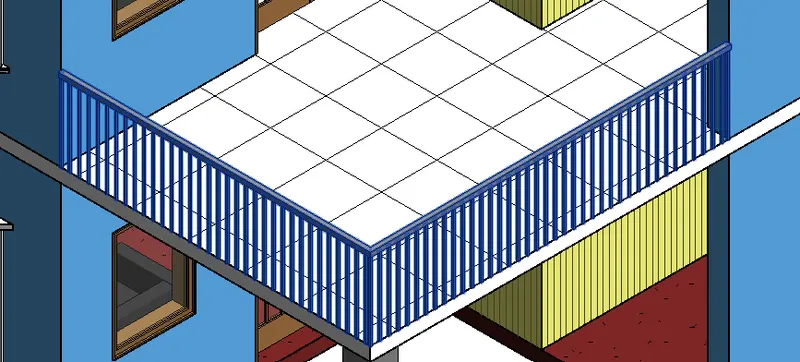
Select ARCHITECTURE Tab
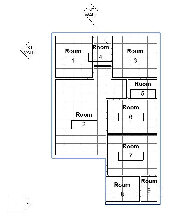
Go to ROOMS and AREA panel and chose ROOM tool.
Mark all the ROOMS
Press ESCAPE
RESULT: -
We created partition walls
We created seperate rooms using partition walls
we created all the mentioned rooms.
We attached Room tags to the rooms created
5Q]
AIM: -
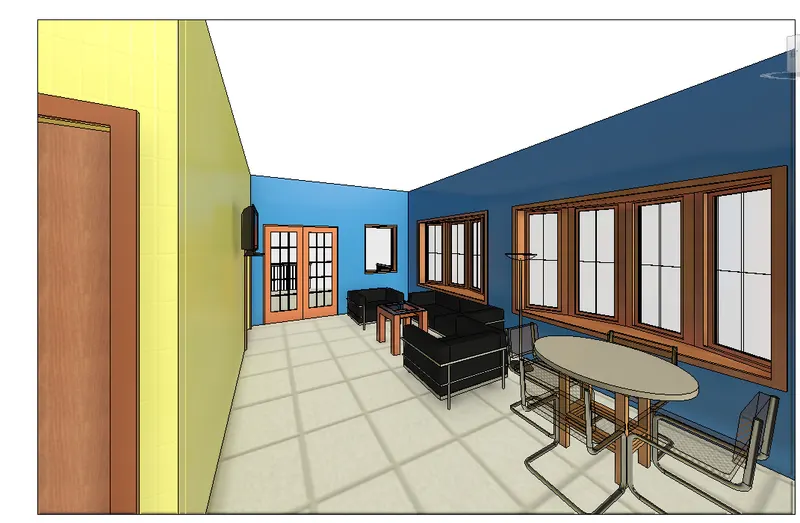
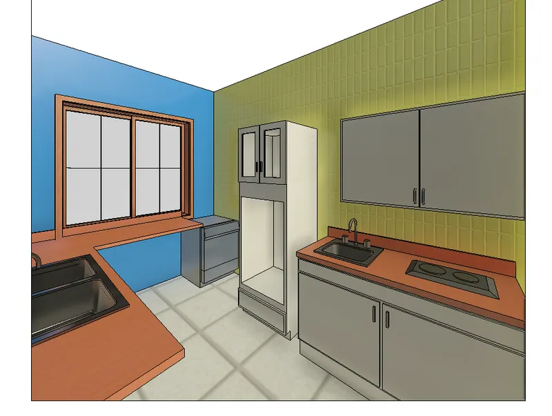
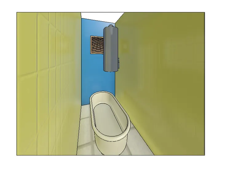
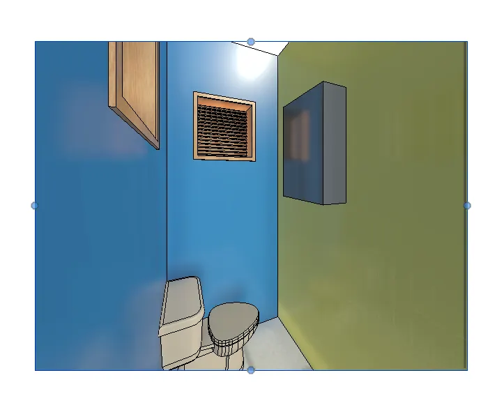
Insert the Residential model elements such as Door, window, Couch, bed etc to the unit.
Save the project.
PROCEDURE: -
Select INSERT tab
Go to Load From Library panel and click on Load Family tool

Load family dialogue box pops on the screen
Open Libraries Folder
In Libraries folder open US IMPERIAL folder
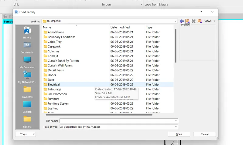
All CATEGORIES are available here
Open Doors Category and select Double-Full-Glass-Wood Family
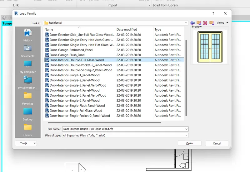
Select one of the Types/Elements from the list.
Choose 72” x 80” Element .
Press OK.
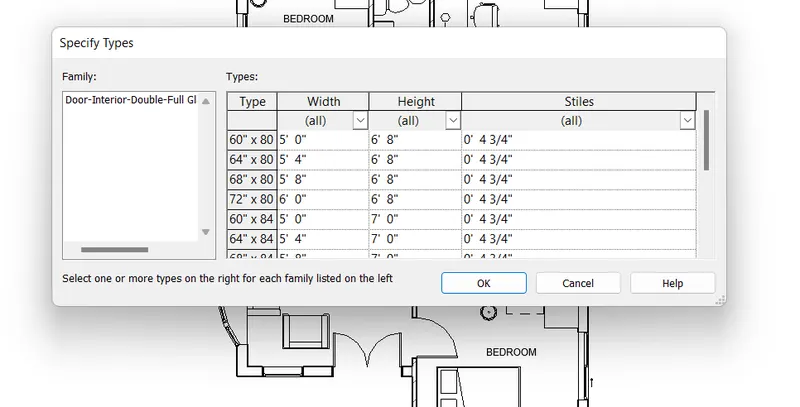
Door Element adds to the Properties browser
Select ARCHITECTURE tab.
Go to BUILD panel and click on Component tool and select Place a component option
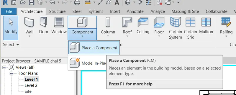
Allt the family elements we selected stores in the Properties Browser.
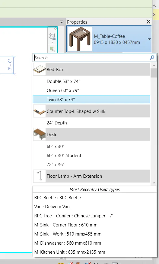
Choose 72” x 80” Element and place at the Entrance.
Press Enter
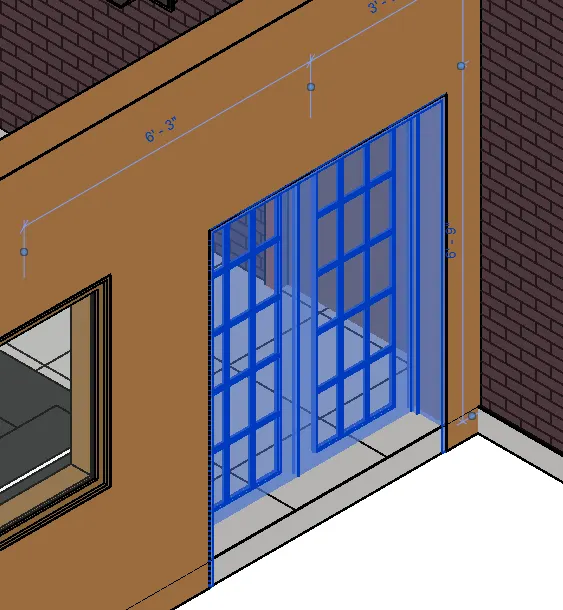
Open Doors Category and select SINGLE FLUSH FAMILY
Choose 36” X 84” Element and place at the Kitchen, Bedrooms.
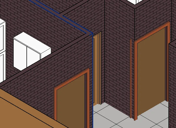
Open Doors Category and select Door Interior Single-1_panel wood FAMILY
Choose 32” X 80” Element and place at the Wash rooms.
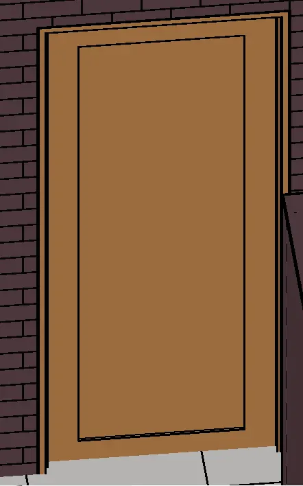
Select INSERT tab
Go to Load From Library panel and click on Load Family tool
Load family dialogue box pops on the screen
Open Libraries Folder
In Libraries folder open US IMPERIAL folder
All CATEGORIES are available here
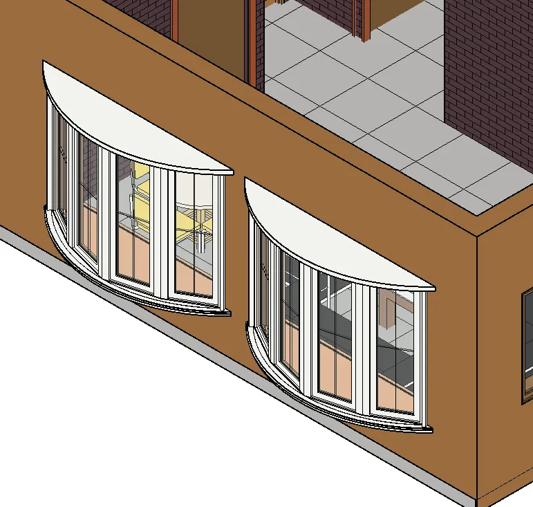
Open WINDOWS Category and select Window Bow Casement family
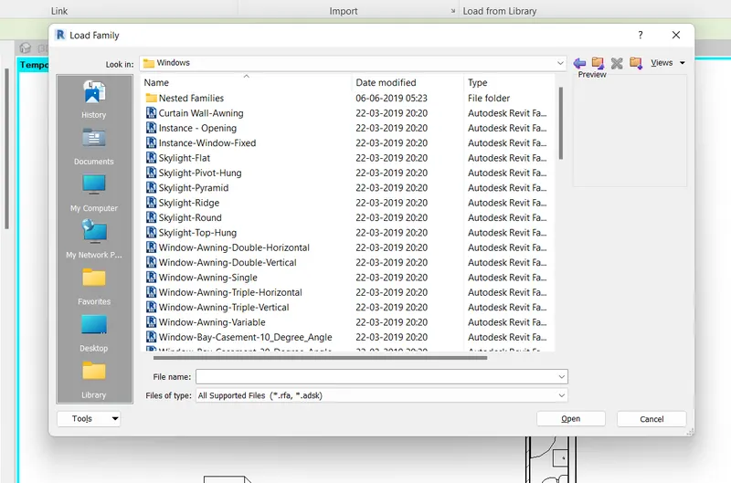
Select one of the Elements from the list.
Choose 80" x 60" element.
Select ARCHITECTURE tab.
Go to BUILD panel and click on Component tool and select Place a component option
Choose 80" x 60" Element in the Properties browser
Mention sill Level: 3' units.
Place the window in the Living Room.
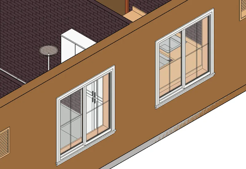
Open Windows Category and select Window Sliding Double Family
Choose 60" x 60" Element and place at the Bedrooms and Kitchen.
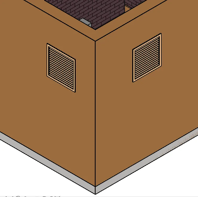
Open Windows Category and select Windoe-Louvers Family
Choose 24" x 24" Element and place at the Wash rooms.
Select INSERT tab
Go to Load From Library panel and click on Load Family tool
Load family dialogue box pops on the screen
Open Libraries Folder
In Libraries folder open US IMPERIAL folder
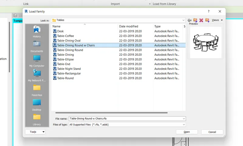
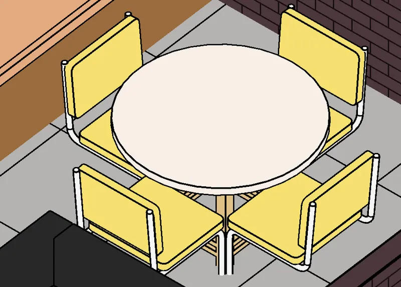
Open Tables Category and select Table Dining Round W chairs Family
Click OK
Select ARCHITECTURE tab.
Go to BUILD panel and click on Component tool and select Place a component option
Choose 36" Diameter Element in the Properties browser
Place the table in the Dining Room.
Open Libraries Folder
In Libraries folder open US IMPERIAL folder
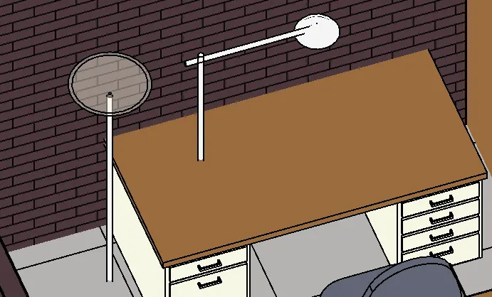
Open Tables Category and select Desk Family.
Choose 60" x 30" student Element in the Properties browser
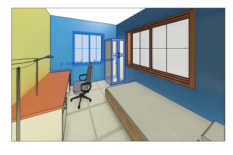
Place it in the bedroom
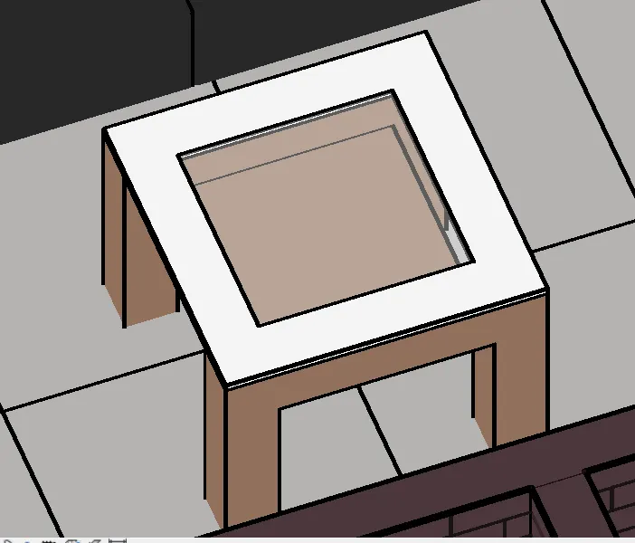
Open Tables Category and select Table-Coffee Family.
Choose 24" x 24" x 24" Element in the Properties browser
Place it in the Living Room.
Select INSERT tab
Go to Load From Library panel and click on Load Family tool
Load family dialogue box pops on the screen
Open Libraries Folder
In Libraries folder open US IMPERIAL folder
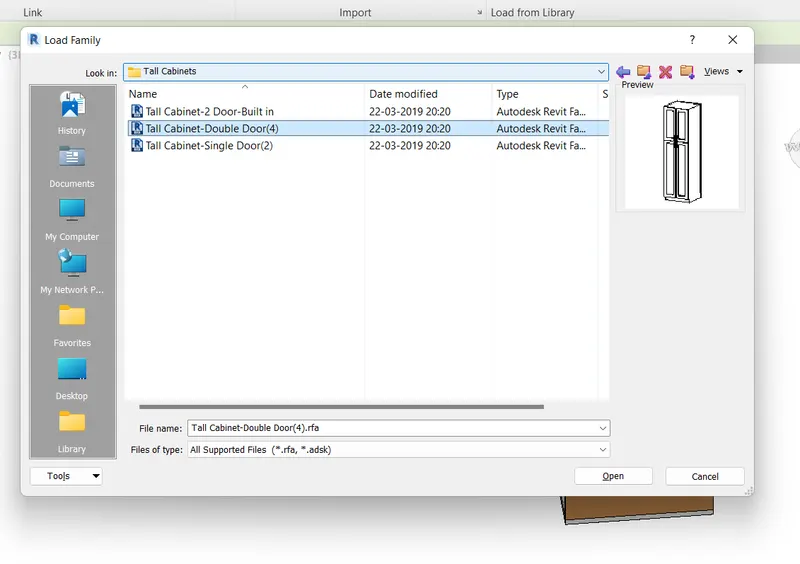
Open Casework Category and select Tall Cabinet Double Door Family
Click OK
Select ARCHITECTURE tab.
Go to BUILD panel and click on Component tool and select Place a component option
Choose 30" Element in the Properties browser
Place the table in the bedrooms.
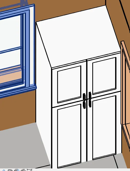
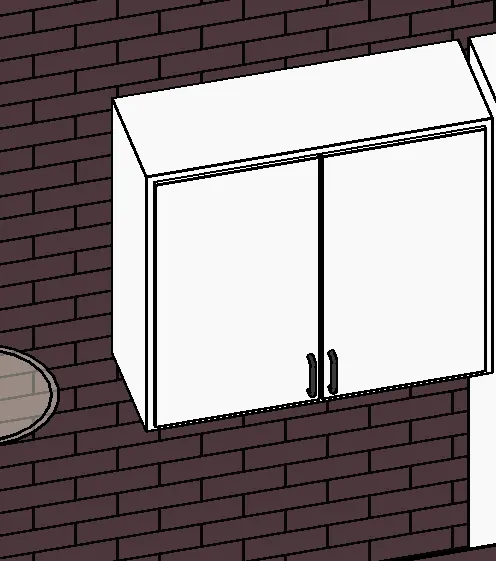
Open WALL CABINET Category and select UPPER CABINET DOUBLE DOOR Family.
Choose 33" Element in the Properties browser
Place it in the Bedroom.
Select INSERT tab
Go to Load From Library panel and click on Load Family tool
Load family dialogue box pops on the screen
Open Libraries Folder
In Libraries folder open US IMPERIAL folder
Open PLUMBING Category
Go to Architectural folder in Plumbing Category
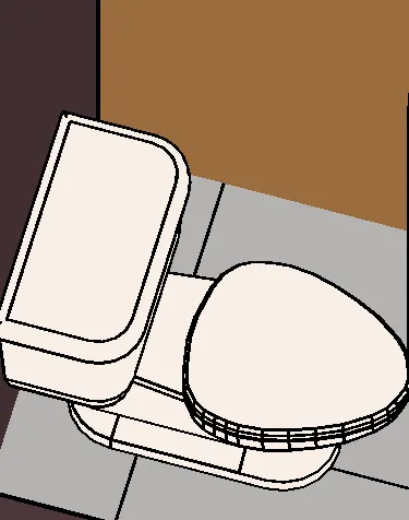
In Architectural folder Select Fixtures and open Water closets
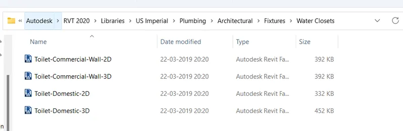
In Water Closets Folder Select Toilet Domestic 3D Family.
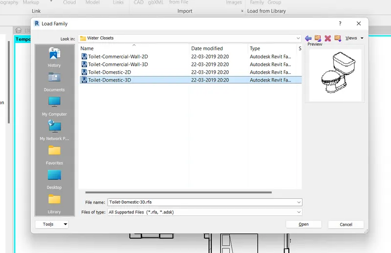
Select ARCHITECTURE tab.
Go to BUILD panel and click on Component tool and select Place a component option
Choose Element in the Properties browser
Place the toilet in the Washrooms.
Open PLUMBING Category
Go to Architectural folder in Plumbing Category
In Architectural folder Select Fixtures and open Sinks
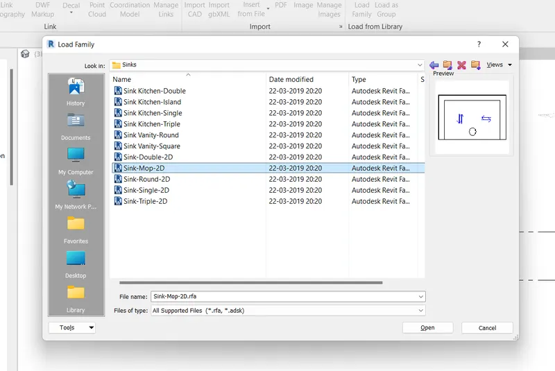
Place the sink in the washrooms.
Open PLUMBING Category
Go to MEP folder in Plumbing Category
In MEP folder Select Fixtures and open EQUIPMENTS Folder
Select Water heaters Family
Choose Water Heater 152 L Element.
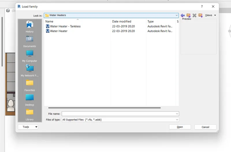
Place the Water heater in the washroom.
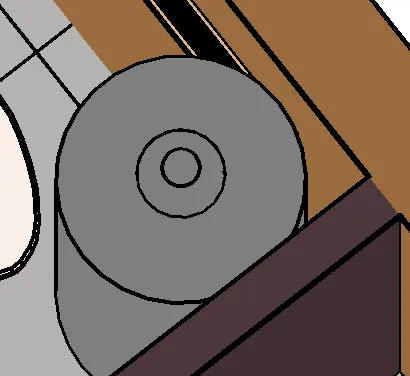
Select INSERT tab
Go to Load From Library panel and click on Load Family tool
Load family dialogue box pops on the screen
Open Libraries Folder
In Libraries folder open US IMPERIAL folder
Open Furniture Category and select Seating Family
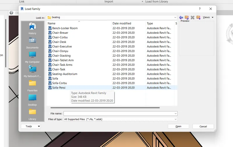
Choose Sofa Corbu Element.
Select ARCHITECTURE tab.
Go to BUILD panel and click on Component tool and select Place a component option
Choose Element in the Properties browser
Place the sofa in the Living room.
In Libraries folder open US IMPERIAL folder
Open Furniture Category and select Seating Family
Choose Chair Corbu Element.
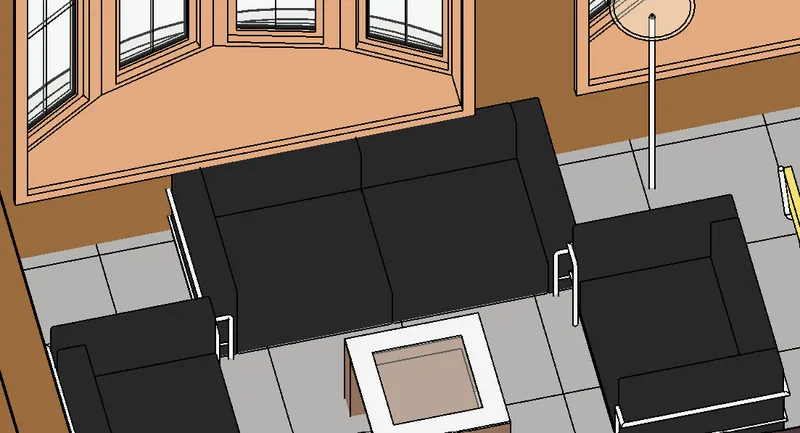
Open Furniture Category and select Seating Family
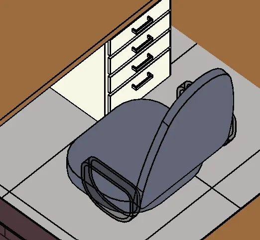
Choose Chair Executive Element.
Place the chair in the bedroom.
Select INSERT tab
Go to Load From Library panel and click on Load Family tool
Load family dialogue box pops on the screen
Open Libraries Folder
In Libraries folder open US IMPERIAL folder
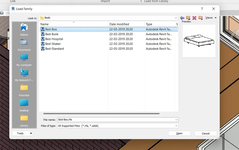
Open Furniture Folder and select BED category
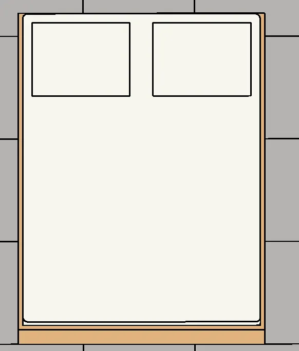
Open Beds Category and select Bed Box Family.
Select ARCHITECTURE tab.
Go to BUILD panel and click on Component tool and select Place a component option
Choose Bed Box Double 53" x 74" Element in the Properties browser
Place the bed in the Bedroom.
Select INSERT tab
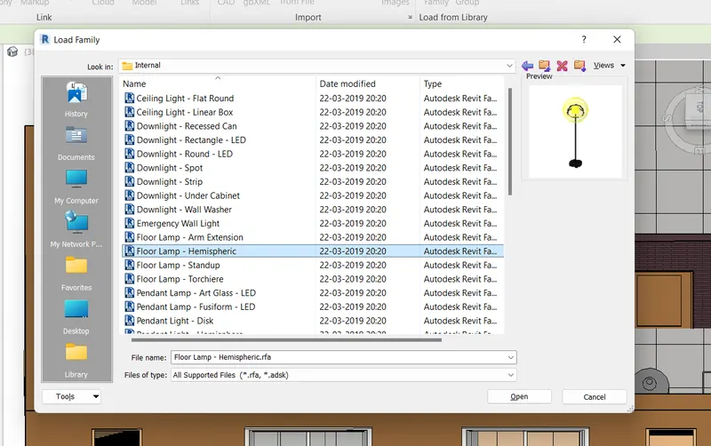
Go to Load From Library panel and click on Load Family tool
Load family dialogue box pops on the screen
Open Libraries Folder
In Libraries folder open US IMPERIAL folder
Open Lights Category and select Floor Lamp-Hemisperic Family
Select ARCHITECTURE tab.
Go to BUILD panel and click on Component tool and select Place a component option
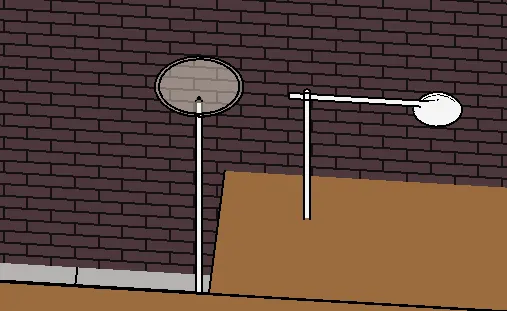
Choose Floor Lamp 277V Element in the Properties browser
Place the Lamp in the Bedrooms and Living Room.
In Libraries folder open US IMPERIAL folder
Open Lights Category and select Floor Lamp-Arm Extension Family
Choose 120V Element and Place it in the Bedroom.
Select INSERT tab
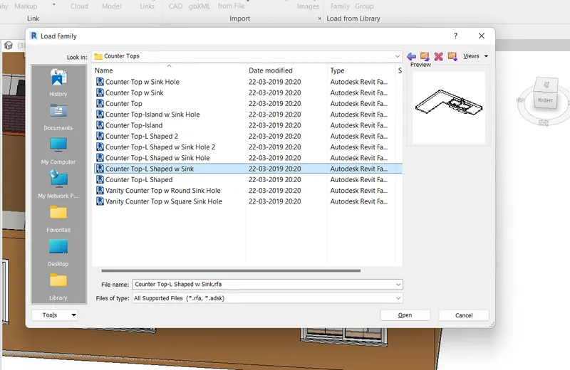
Go to Load From Library panel and click on Load Family tool
Load family dialogue box pops on the screen
Open Libraries Folder
In Libraries folder open US IMPERIAL folder
Open Casework folder
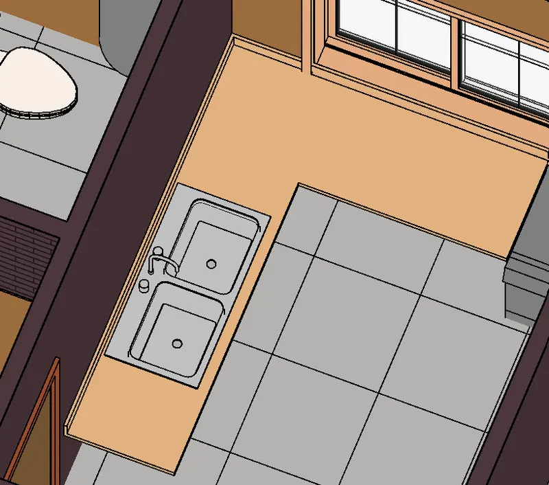
Open COUNTER TOP Category and select COUNTER TOP L SHAPED W SINK HOLE Family
Select ARCHITECTURE tab.
Go to BUILD panel and click on Component tool and select Place a component option
Choose Counter Top L shaped 24" depth Element in the Properties browser
Place it in the Kitchen.
Select ARCHITECTURE tab.
Go to BUILD panel and click on Component tool and select Place a component option
Choose freezer in the Properties browser
Place it in the Kitchen.
Select ARCHITECTURE tab.
Go to BUILD panel and click on Component tool and select Place a component option
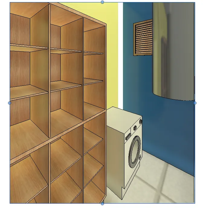
Choose washing machine in the Properties browser
Place it in the washroom.
Select ARCHITECTURE Tab
Go to component panel and choose model in place option
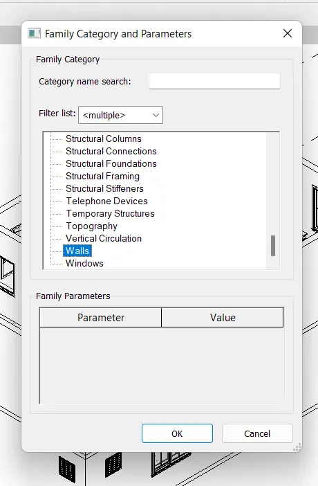
Family Category and Parameters box opens
Selct WALLS
and press OK
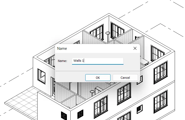
Type the name as WALLS-1
Press OK
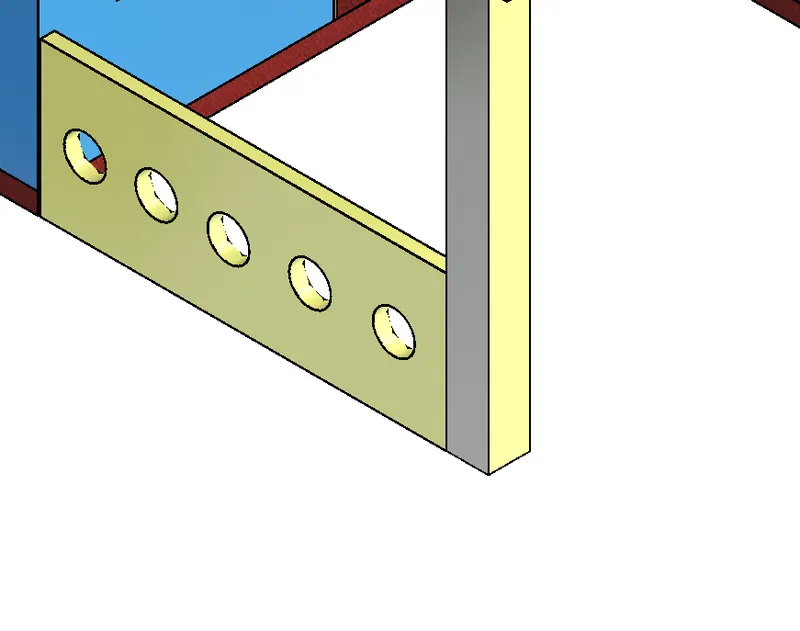
In MODEL PANEL Select OPENING tool
In MODIFY tab,go to DRAW panel and select Circle

Draw circles on the wall at the Entrance porch
Press ENTER
RESULT: -
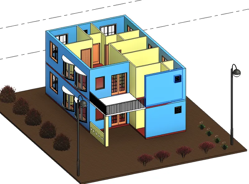
We added Residential model elements to the Residential Unit using INSERT tab and Libraries available.
Included all the elements mentioned in the question.