Creating Walls, Partition walls and Floors for a residential layout using REVIT
1) Use the project file created from Week 2. Use it for this assignment. Based on your layout from week 2, using floor tool under architecture tab and select the floor with appropriate material and thickness using the property browser create a layout in the Ground floor Level. Align the floor plan with grids created from week 2
AIM:
To create a floor plan and need to apply the materials and thickness using the property browser and to align the floor plan with grids created in week 2
INTRODUCTION:
Building material is materials used in construction. Many naturally occuring substances such as clay, rocks, sand woodetc which are used to construct the buildings.
Apart from naturally occuring materials many man made products are in use , some more and some less synthetic
Floor plans are the most critical elements of our building plans. Drawn to scale and shown from above floor plans illustrate how rooms, space, and physical features work in relation to each other within the home
They are the key docments that show how people will move through the space and interact with their home
Floor plans show the extent to which a space will work for its intended puropses
PROCEDURE:
STEP 1
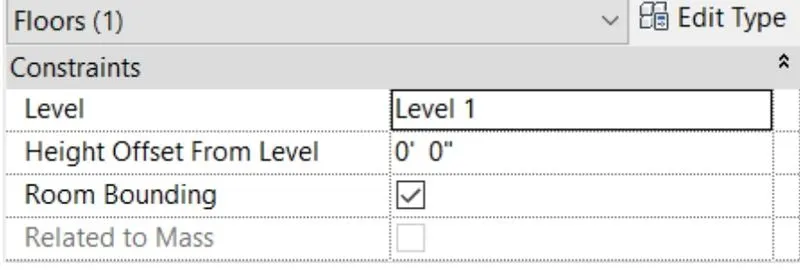
First we select the floor as shown below
After selecting the floor , click the edit type from the properties browser as shown below
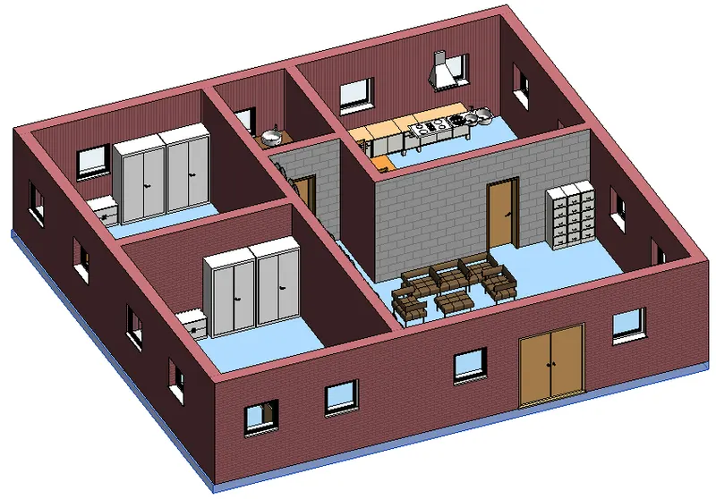
IN THE 3D VIEW IT SHOWS LIKE
STEP 2
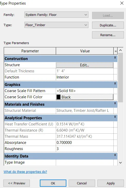
After clicking the edit type option, the type properties tab will be visible on the screen shown below
Next we change the material type by clicking the edit option as shown below
STEP 3:
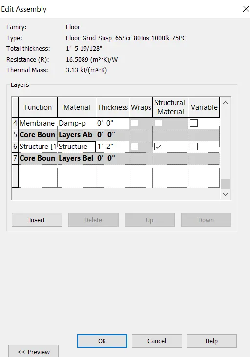
After clicking the edit option the edit assembly tab appears
We select the material type in 2nd room as shown below
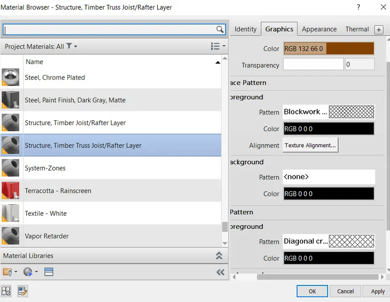
After clicking that the material browser appears,then select the material type as Timber and choose the colour as per our choice
SELECT THE DESIRED MATERIAL
STEP 4:
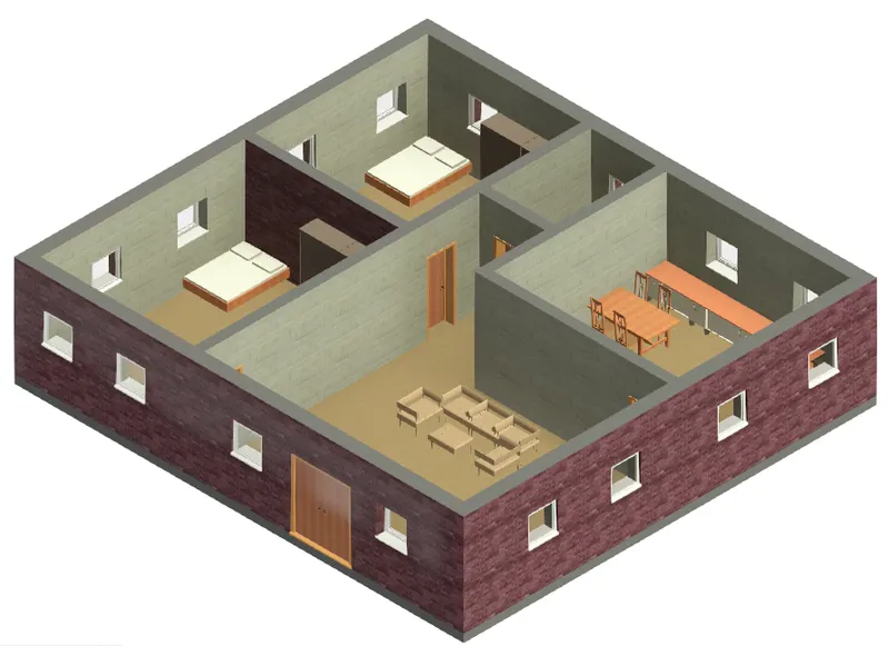
Finally the material is applied to the floor as shown below
STEP 5:
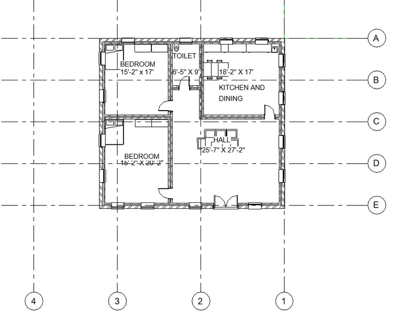
Next floor plan is aligned to the grids as shown in the figure below
RESULT
The materials are applied to the floor and the floor plan is sucessfully aligned with the grids
2) Add walls based on the floor layout. Pick lines or use the draw tool to modify the boundary of walls. Use the property browser to select appropriate material and thickness for walls. After creating the walls verify using the property browser to see if the top and bottom of the walls are constrained.
a. Based on your observation, what is beneficial for connecting walls with associated levels rather than being Unconnected
b. Which option is convenient for modeling walls, By Height or By Depth?
AIM: To create a floor plan and need to apply the materials and thickness using the property browser for walls
Verify using the property browser to see if the top and bottom of the walls are constrained
Need to understand the benifits of connecting walls with associated levels rather than being unnocted
Need to know which option is convinient for modelling walls,By height or depth
INTRODUCTION:
Walls are arguably one of the most important elements of any building
As such the wall tool is a prominient function of Autodesk Revit Architecture
Building materials is used for construction . Many naturally occuring substances such as clay, rocks, sand wood etc have been used to construct buildings
Apart from naturally occuring materials many man made products are in use, some more and some less synthetic
PROCEDURE:
STEP 1
First we select the wall as shown below
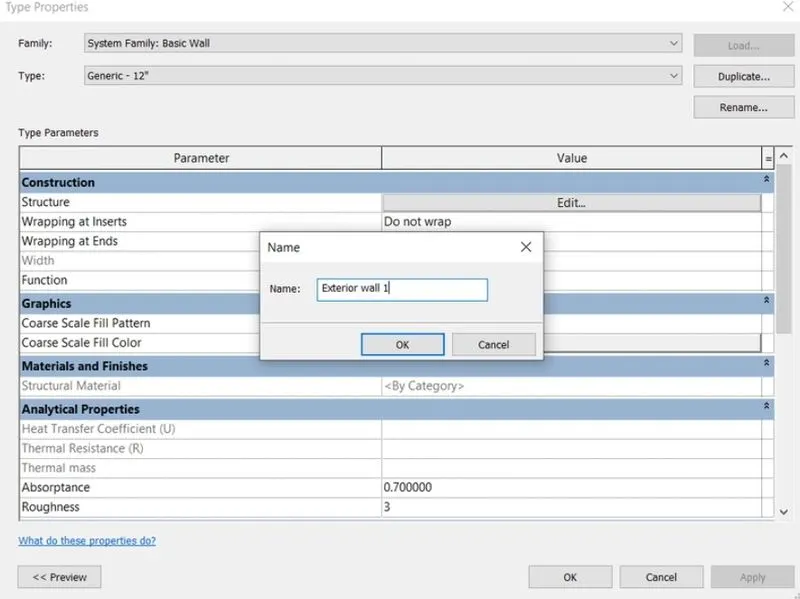
After selecting the wall, click the edit type from the properties browser as shown below
STEP 2
After clicking the edit option the edit assembly tab appears
We select the material type in 2nd room as shown below
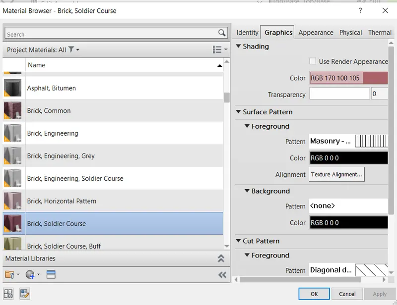
After clicking that the material browser appears then select the material type as brick, soldier course as shown below
STEP 3
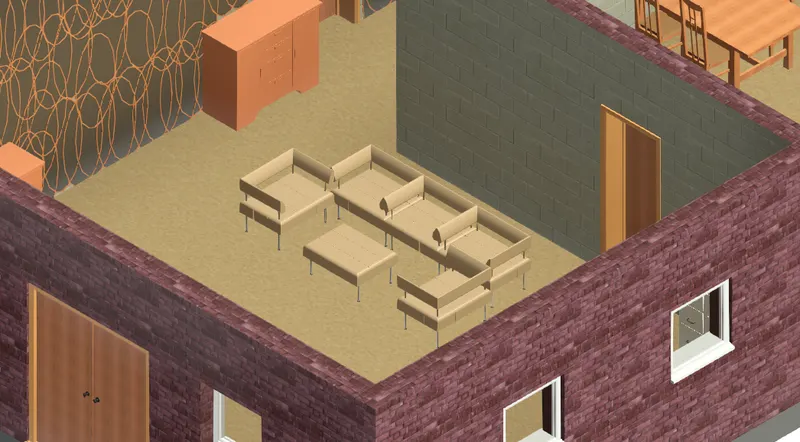
After applying the materials to the walls we need to zoom the wall to see the material type very closely as shown below
STEP 4:
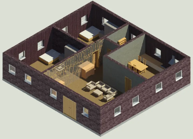
Finally the material have been applied to the walls as shown below
STEP 5:
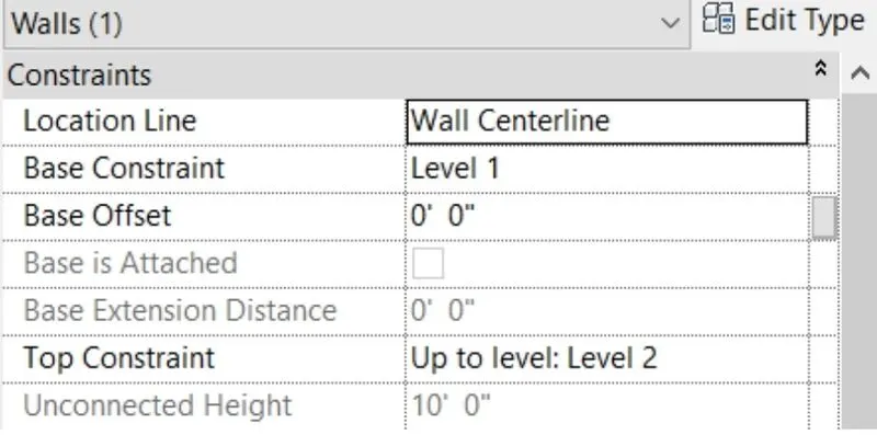
a. Based on your observation, what is beneficial for connecting walls with associated levels rather than being Unconnected
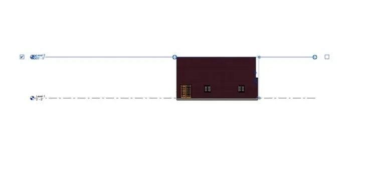
If we select the top constraint as up to level 2 , the height of the wall changes with the levels
When we put the level height to the 20' then height of the wall is also changed to 20' as shown below
The height of level is changed and the height of the wall is also changed as shown in the figure
If we select the top constraints as unconnected , The height of the wall doesnt changes with the levels
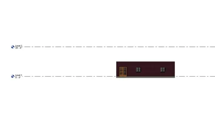
When we put the level height to the 20' the only level height is changed the wall height will not be changed
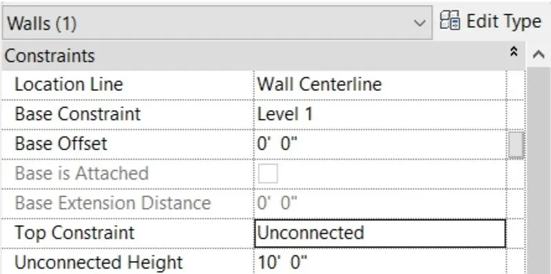
The height of level is changed and the height of the wall will not change as shown on the below figure
STEP 6:
Which option is convenient for modeling walls, By Height or By Depth?
When we select the height option for the wall,The wall will be created above the level as shown
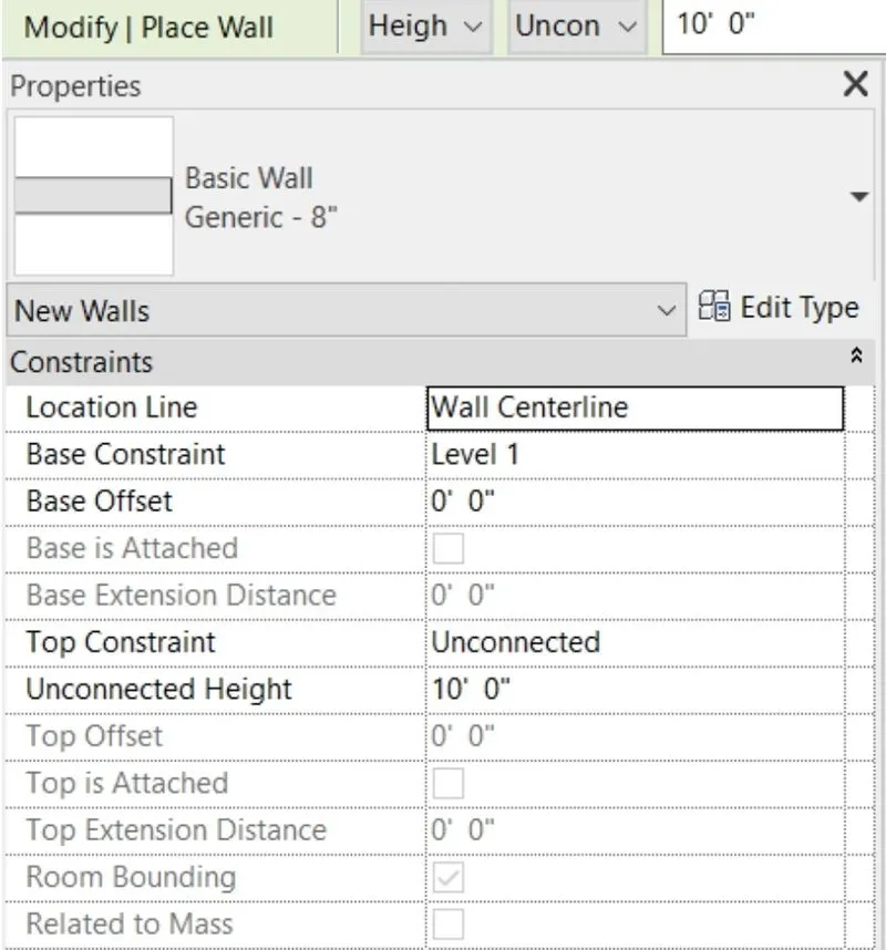
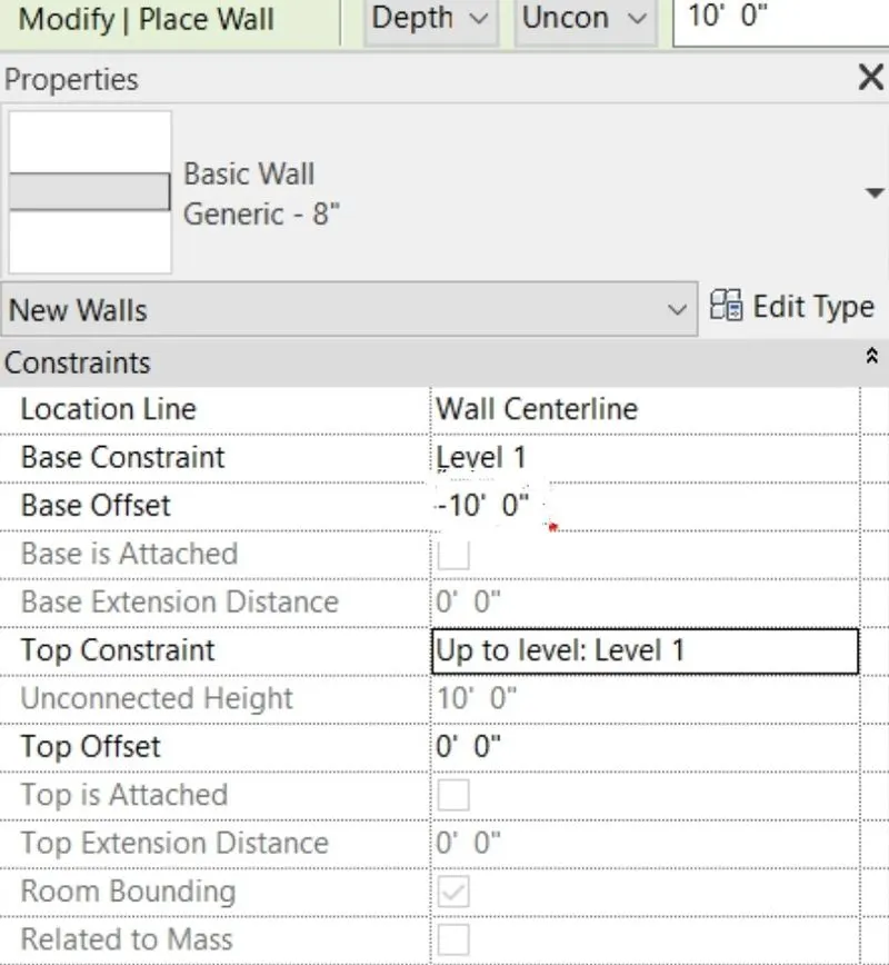
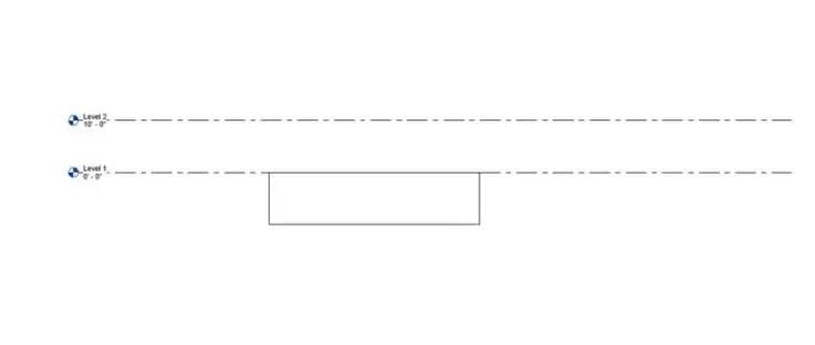
When we select the height option for the wall,The wall will be created below the level as shown below
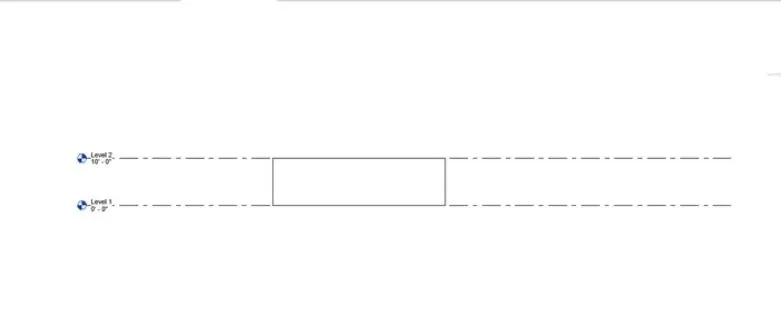
When we select the height option for the wall. The wall will be created below the level as shown below
RESULT:
Sucessfully applied materials to the wall
The top and bottom of the walls are constrained
Benificial for connecting walls with associated levels is when level height changes the wall height changes
Height option is convenient for modelling walls
3) Copy the model elements ( wall, floor ) modelled to Ground Floor Level and paste it aligned to First Floor Level . Use modify tab to utilize copy and paste options to align
elements to a different level
AIM:
Use modify tab to utilize copy and paste options to align to align elements to a different level
INTRODUCTION:
In architecture and building engineering, a floor plan is a technical drawing to scale, showing a view from above, of the relationships between rooms, spaces, traffic patterns, and other physical features at one level of a structure.
Dimensions are usually drawn between the walls to specify room sizes and wall lengths. Floor plans may also include details of fixtures like sinks, water heaters, furnaces, etc. Floor plans may include notes for construction to specify finishes, construction methods, or symbols for electrical items.
It is also called a plan which is a measured plane typically projected at the floor height as opposed to an elevation which is a measured plane projected from the side of a building, along its height, or a section or cross section where a building is cut along an axis to reveal the interior structure.
PROCEDURE:
STEP 1
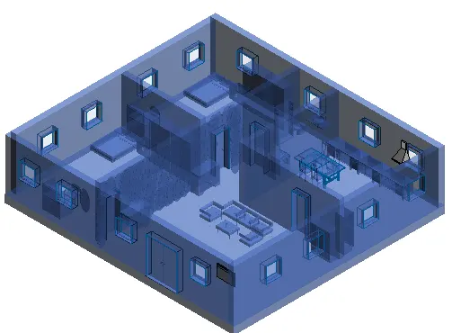
First we select the total groundfloor, then the groundfloor is copied to clipboard
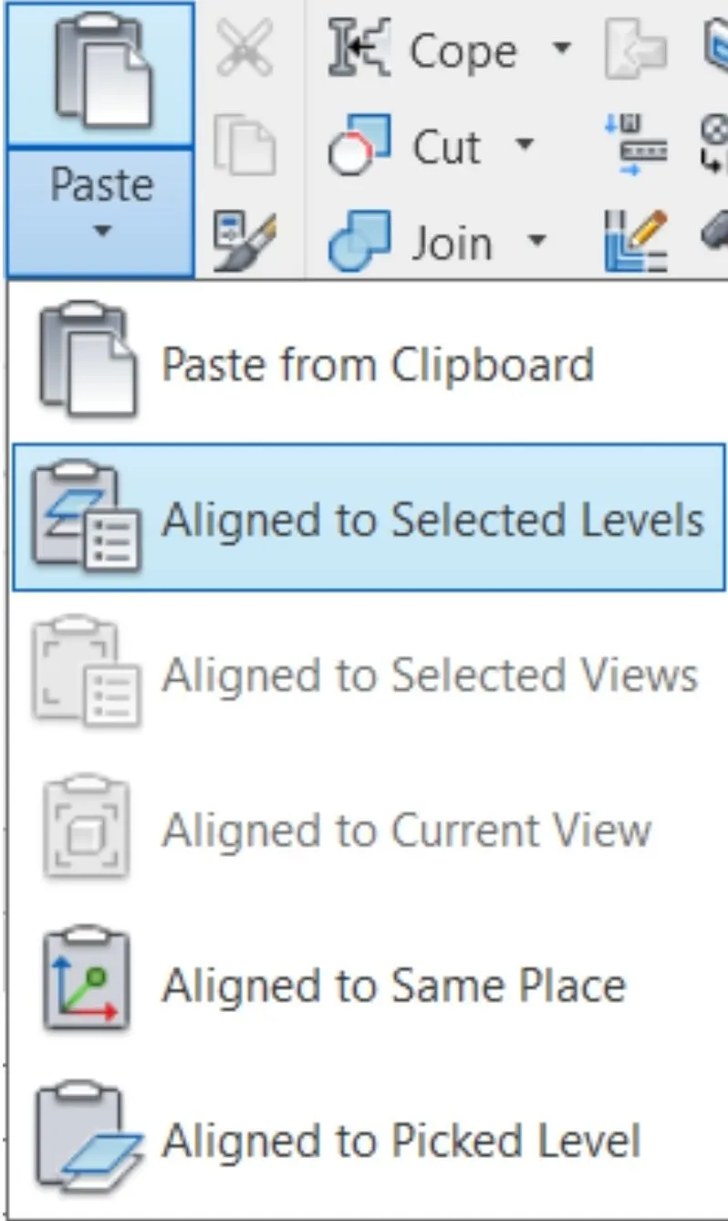
Then use the paste option to align elements to a different level as shown below
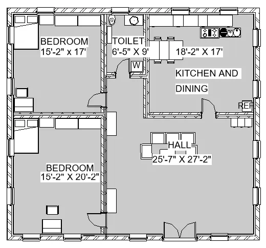
STEP 2
Next use the paste option to align elements to a different level as shown below
STEP 3
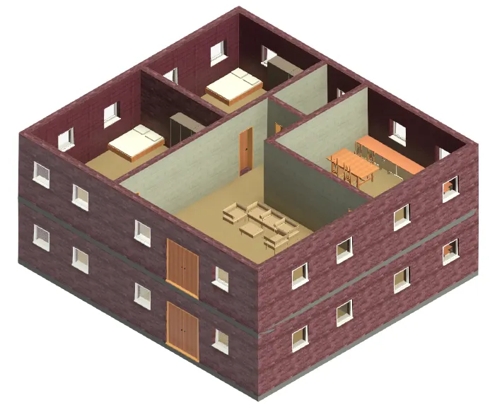
Finally the elements are aligned to the different level as shown in the below figure
RESULT:
The elements are sucessfully aligned to the different level using the copy and paste options
4) Use interior partition walls to create separate rooms within your residential unit. The model must include the following rooms
a. Living Room/ Drawing Room ( 15’ X 18’)
b. Dining Room (9’ X 11’)
c. Bed Room ( 9’ X 12’ and 15’ X 11’)
d. Rest Room ( 10’ X 12’ )
e. Kitchen (8’ X 10’)
The above are for examples. You can use them or use your measured entities to create your model based on your layout. You may include entry walkway, Patios or Guest
rooms based on your creativity and purpose of modeling. Convert units if you are using metric system
AIM: To create separate rooms within your residential unit using interior partition walls
INTRODUCTION:
Partitions are non-load bearing walls that separate spaces in buildings. As well as spatial division, they can provide; privacy, acoustic and fire separation and flexibility of layout.
Partition walls can be solid, typically constructed from brick or blockwork, or can be a framed construction. Framed partition walls are sometimes referred to as stud walls, and can be constructed from a timber, steel or aluminium frames clad with boarding such as plasterboard, timber, metal or fibreboard. Partition walls may also be glazed.
They may be purpose-designed and constructed or may be modular systems, and can incorporate openings, windows, doors, ducting, pipework, sockets, wiring, skirting, architraves and so on.
As they are non-load bearing, partition walls can provide good flexibility, particularly if they are lightweight, framed systems, as wall positions can be changed relatively easily and inexpensively without impacting on the overall structure of a building. Depending on the nature of the construction, it may be possible to re-use some, or all of the components of the wall in a different location.
PROCEDURE:
STEP 1
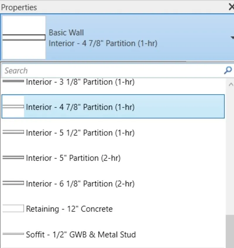
First select the interior wall and change the wall type as partition wall as shown below
STEP 2
The interior partition walls are created as shown in the below screenshot
RESULT
The interior partition walls are sucessfully created
5) Based on week 2 assignment, the components to be included in a residential unit were inserted to the Revit file. Place these components in appropriate locations to add details to your residential model
a. Place Doors and windows in the wall at appropriate locations
b. The Living Room must include furniture set, couch table and TV desk and shelf cabinets
c. The Dining Room must include a table and chairs serving the purpose of eating
d. Bed Room must include a bed set, shelf, lighting and individual study desk and chair
e. Rest room should include bath tub and plumbing fixtures discussed in class
f. Kitchen should include countertops, gas stove cabinet and shelves to store food items
g. The wash/storage room can include washing machines and shelves to store clothes
All the components are available in Revit Library. Use them to place at appropriate locations to add details to your model. Use 3D navigation to check the model and its authenticity on a real time basis to verify the model
AIM:
To insert the components in appropriate locations to add details to the residential model, based on the week2 assignment
INTRODUCTION:
The residential model components are furniture set, couch table , TV desk , Shelf cabinets, table and chairs serving the purpose of eating,a bed set, shelf, lighting and individual study desk and chair, bath tub and plumbing fixtures , countertops, gas stove cabinet and shelves , washing machines and shelves to store clothes
These components are very importatnt in the building model for construction
Coming to the 3d modelling in the revit these components are present in the library and we need to insert them into the model
PROCEDURE:
STEP 1
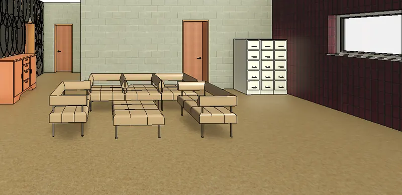
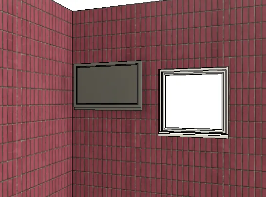
First we insert the furniture components in the hall as shown below - TV , FURNITURE etc
STEP2
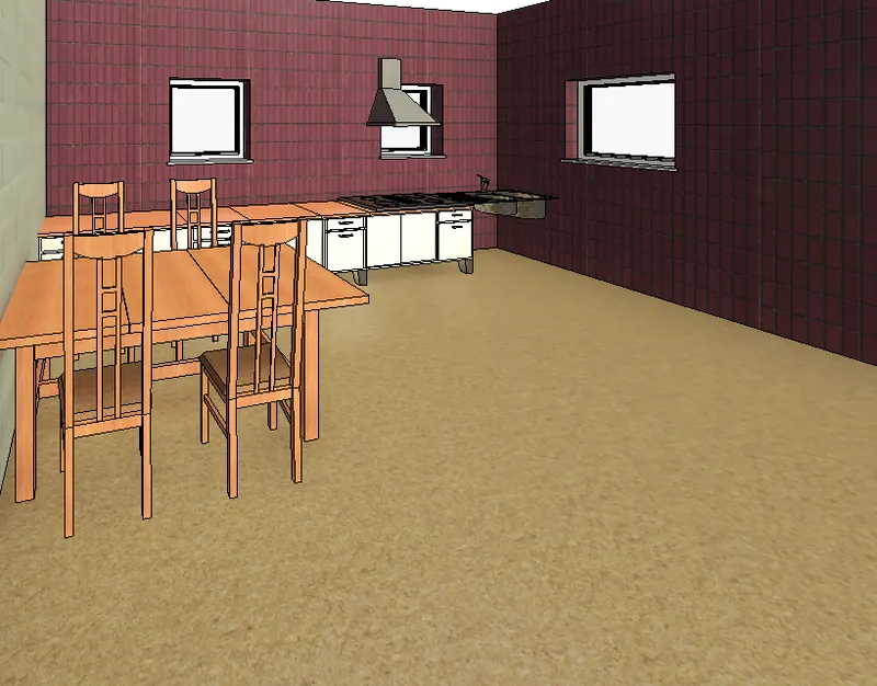
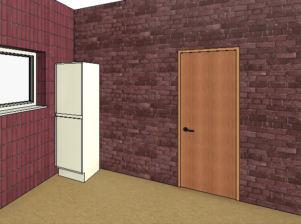
Next we insert the kitchen components from the library as shown in the picture- cooktop,dining table, chimney,sink,refrigrator
STEP 3
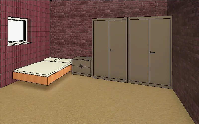
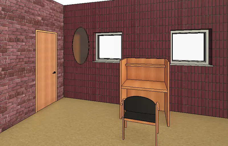
Now in the bedroom components from the library as shown in the picture- bed, sidetable, cupboard, studytable, mirror
STEP4
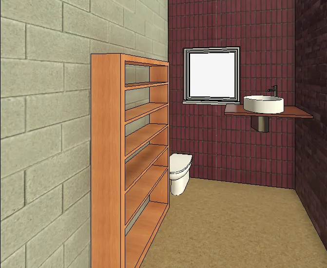
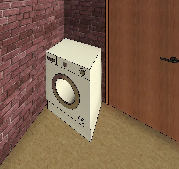
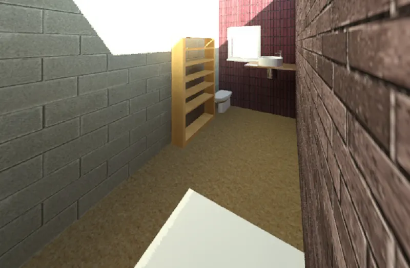
Now insert the components in the bathroom - shelf, w/c, sink,washing machine
STEP 5:
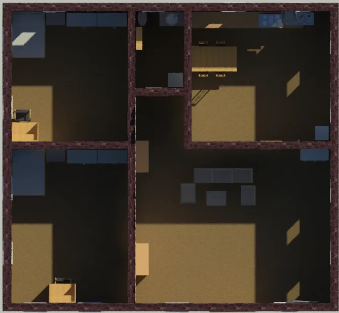
The componenets are inserterd from the library as shown in the figure below
STEP 6:
The layout is turned to the 3D view and the components will be visible in the view
STEP 7:
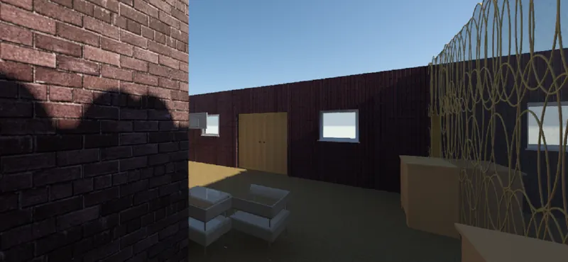
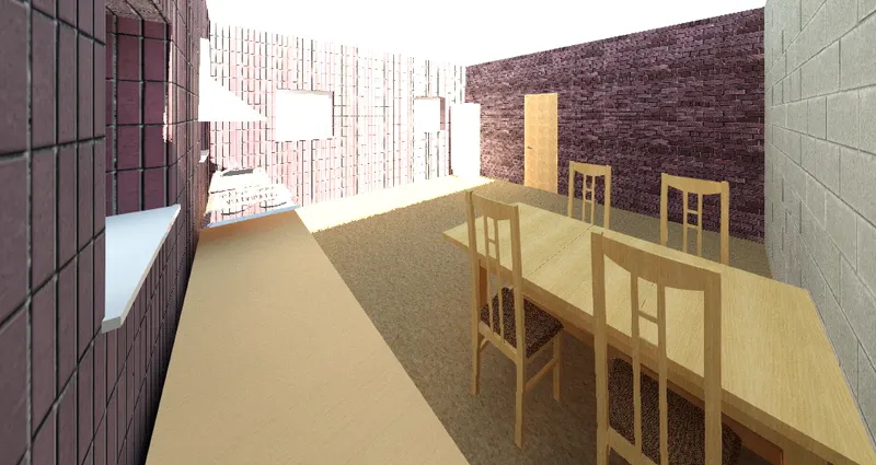
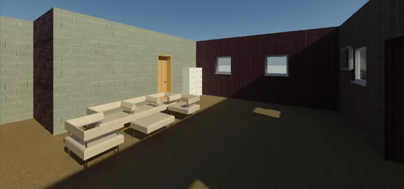
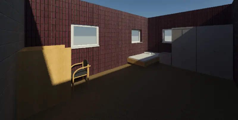
RENDERING
Rendering can offer a quick turnaround time, quality performance, and user friendliness. It can help drive efficiency and accuracy throughout the design process as updates to floor plans, elevations, and sections can be made as the model develops.
Go to VIEW> open the 3d view panel
Go to camera
Place the camera accordingly
Click on render
Click OK
RESULT:
All components are inserted sucessfully from the library in the systematic manner and rendering is also done