Creating Walls, Partition walls and Floors for a residential layout using REVIT
1) Use the project file created from Week 2. Use it for this assignment. Based on your layout from week 2, using floor tool under architecture tab and select the floor with appropriate material and thickness using the property browser create a layout in the Ground floor Level. Align the floor plan with grids created from week 2
Aim : To create a layout in the ground floor and assign the floor with appropriate material and thickness using the property browser and to align floor plan with grids created from week 2 in Revit software.
Introduction :
- Floor is the flat surface which acts as a support to the components above it.
- In Revit software we can create floor using the architecture tab and apply them different materials as per out requirement along with changing the thickness of floor.
Procedure :
Step 1 :
- Open Revit software, click on the challenge of week 2 naming as Residential unit 1
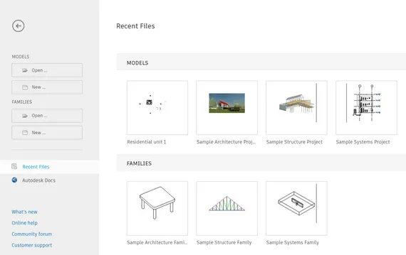
Step 2 :
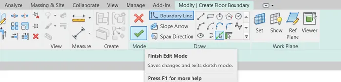
- Go to Architecture tab, select the floor tool from build panel, select the floor Architectural it will open modify floor ribbon.
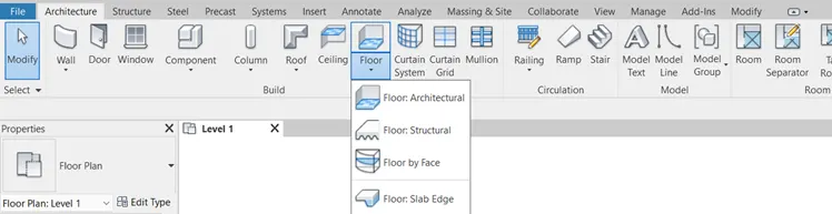
Step 3 :
- Select the pick line option from draw panel.

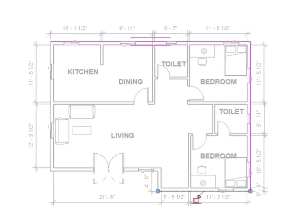
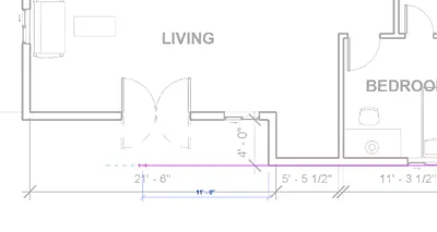
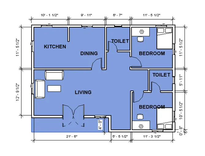
- Now select the line option and draw the floor for patio and remaining wall using the line tool from draw panel to close the floor.
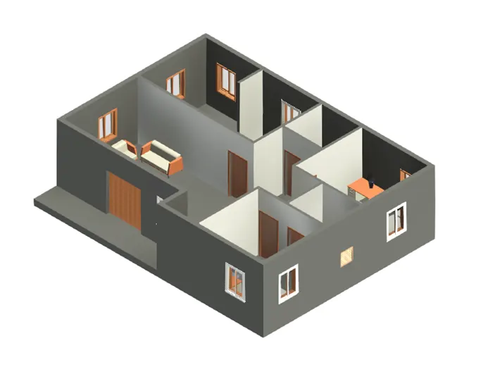
- 3D view of the created floor is shown below.
Step 3:
- For changing the thickness and material of floor, select the floor, go to edit type option from properties window it will open the type properties dialog box.
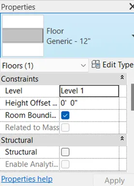
Step 4:
- Select the duplicate option from type property dialog box.
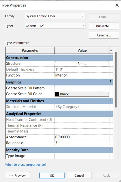
- Edit the name to Generic – 4” and select ok.
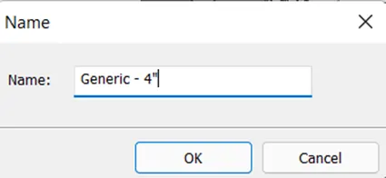
Step 5:
- Select the edit option from type properties dialog box.
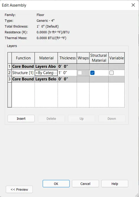
- Select three dots of by category option to change the floor material it will open the material browser dialog box.
- From material browser dialog box, select the material as oak flooring and select ok.
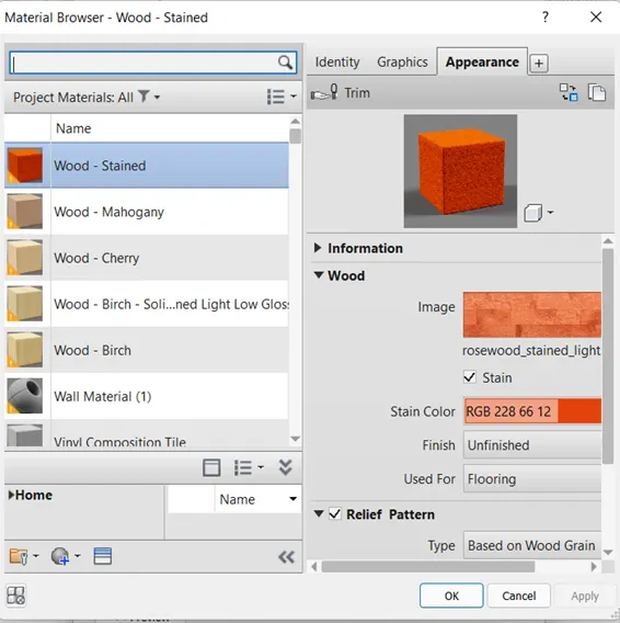
Step 6:
- Again from edit assembly dialog box change the thickness to 4” and select ok it will open the type property dialog box.
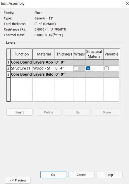
Step 7:
- Select the rename option from type property dialog box, and rename it as Generic – 4” and select ok it will open again the type property dialog box, select ok from it.
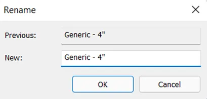
Step 8 :
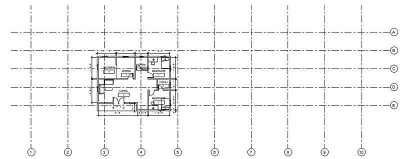
- Floor plan view of floor is shown below.
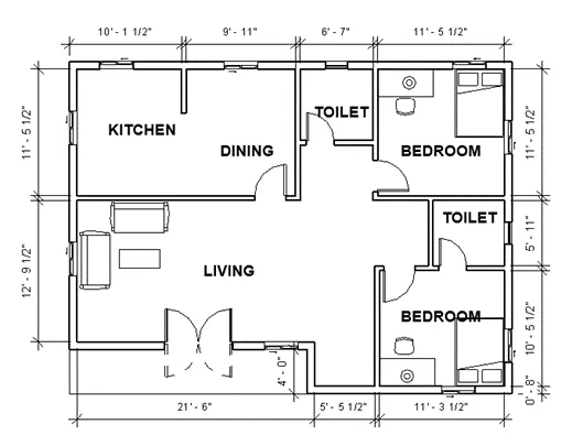
Step 9
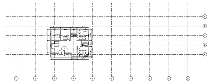
- Floor plan aligned with grids created in week 2 is shown below.
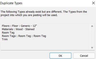
- For aligning the floor plan on the grids created in challenge 2, open challenge 2 file of the grids and go to floor plan view of residential file, select the floor plan, go to modify tab, select the copy to clipboard tool from clipboard panel, select the drop down of paste tool from same panel, select align to selected view option and select the view from dialog box, and select ok.
Result :
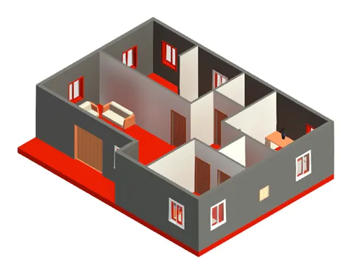
The output in the Revit software by following the above steps in 3D realistic view is shown below.
- Floor plan without grids
- Floor plan with grids
- 3D view of model
2) Add walls based on the floor layout. Pick lines or use the draw tool to modify the boundary of walls. Use the property browser to select appropriate material and thickness for walls. After creating the walls verify using the property browser to see if the top and bottom of the walls are constrained.
- Based on your observation, what is beneficial for connecting walls with associated levels rather than being Unconnected
b. Which option is convenient for modeling walls, By Height or By Depth?
Aim :
- To add walls based on floor layout and apply them appropriate materials in Revit software.
- To observe beneficial modelling practice for connecting walls with associated levels rather than being unconnected
- To understand convenient option for modelling between depth and height.
Introduction:
- Revit software we can apply different materials to the walls to make it more realistic.
- By using Edit type option from property window we can use different materials which are already loaded in the Revit database or we can customize it as per our requirement.
Procedure :
Step 1
- Open the Revit software, select open and select one of the backup file of week 2 challenge naming as residential unit and open it.
- Go to file menu and select save as option then select project and then give name to it as Residential unit 2 and select save.
Step 2 : creating the floor layout
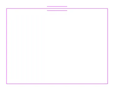
- For drawing the layout of floor, select the Architecture tab, select floor tool from the build panel, select the line option from draw panel of modify floor ribbon and select the rectangle option from draw panel and draw the floor of size 40’ x 30’ as shown below and select right symbol from mode panel.
Step 3 : creating of the exterior wall.
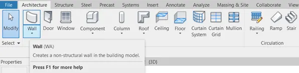
- Go to Architecture tab, select the wall tool from build panel.
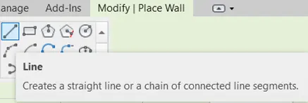
- Select the line tool from draw pane.
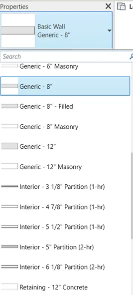
- Select the wall type as Generic – 8” wall and location line as finish face exterior option from properties window and select apply.
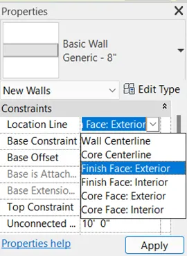
- Draw the exterior wall of 8” thickness by tracing dimensions in the floor layout as shown below.
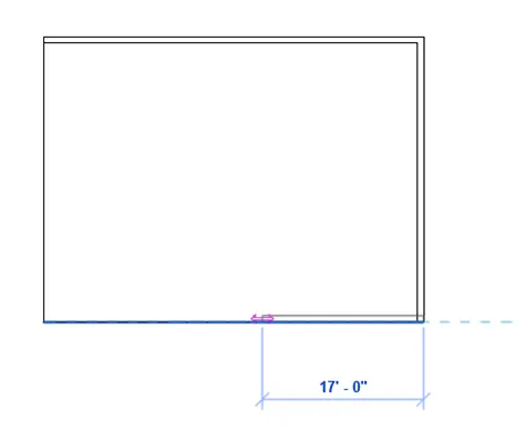
- Similarly draw the other exterior walls of the layout using the similar procedure as shown below and press esc.
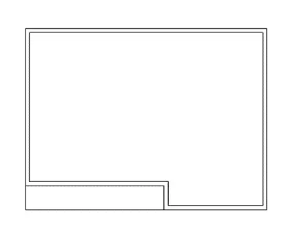
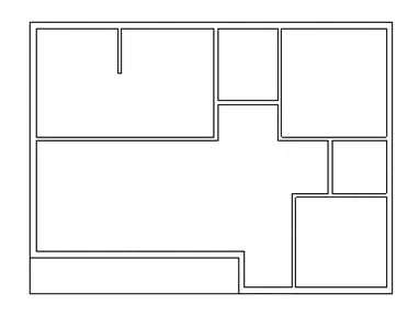
Step 3 : creating of the interior partition walls
- Select the Architecture tab, select wall tool from the build panel, select the line tool from draw panel as mentioned above.
- Select the wall type as Interior – 5” – partition and draw the partition wall according to layout wherever required as shown below.
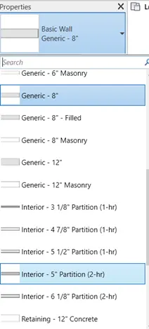
Step 4 :
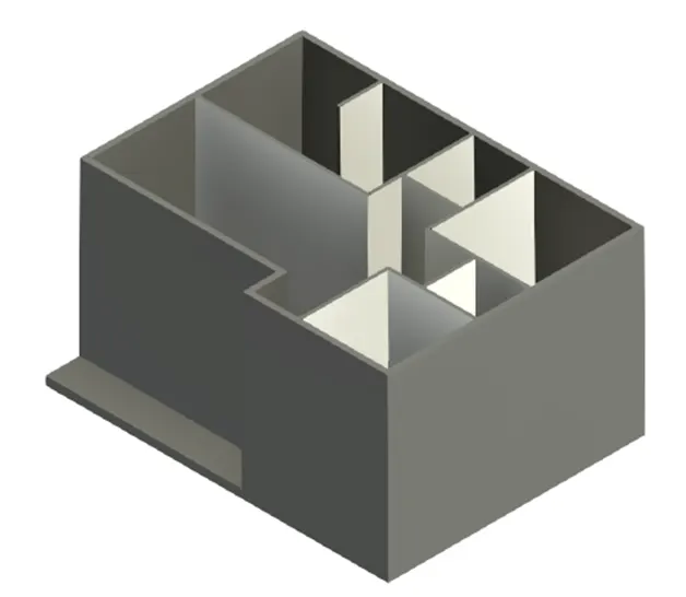
- 3D realistic view of layout of plan.
Step 5
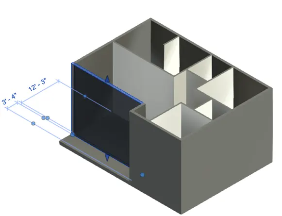
- For observing the top and bottom constrains of the wall select one of the wall as shown below.
Step 6
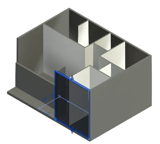
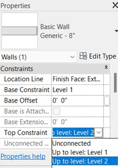
- Similarly, set the top constrain to up to level 2 option from properties window and press enter.
Step 7
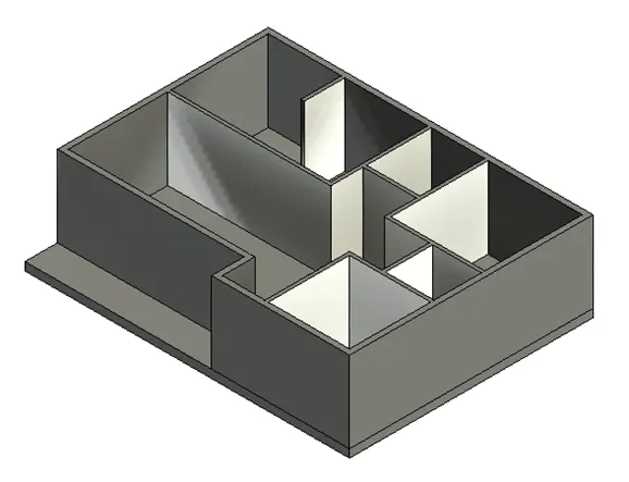
- Similarly set the top constrains of all other walls up to level 2 by using the same procedure as mentioned above.
Step 8
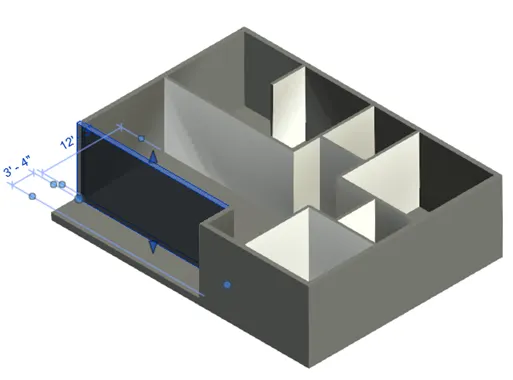
- To apply material to walls, select one of the wall of the layout in 3D view.
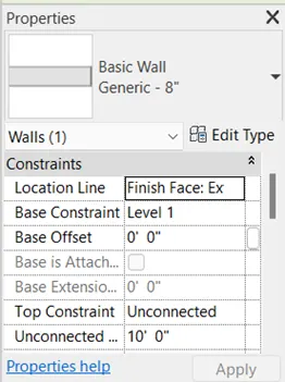
- From properties window, select the edit type option, it will open the type properties dialog box.
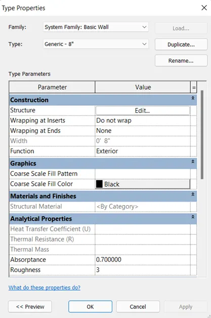
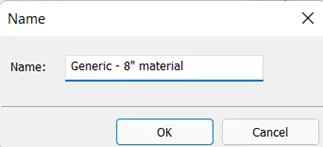
- Select the duplicate option from the dialog box, and name it as Generic – 8” material.
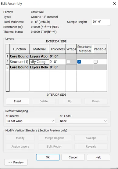
- Select the edit option from type properties dialog box, it will open the Edit Assembly dialog box.
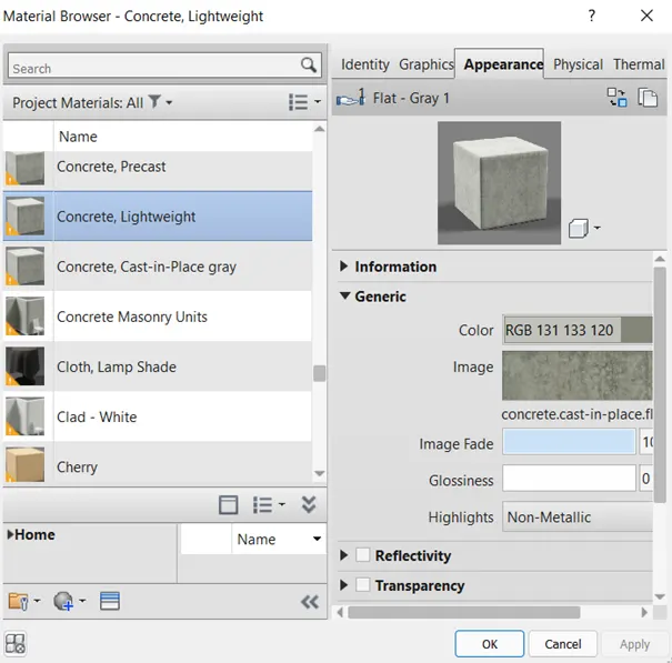
- Select on 3 dots of by category to apply the materials to the wall and chose the material as concrete lightweight and select ok.
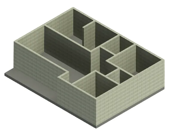
- Select ok from Edit assembly dialog box and select apply and ok from type properties dialog box. Similarly apply the materials to all other walls by using match properties tool from the clipboard panel of modify tab the result is as shown below.
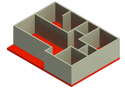
- Similarly apply the materials to the floor as wood stained and edit the thickness of the floor to 4” using edit property option from the properties window as shown below.
- Benefits of connecting walls with associated levels rather than being unconnected
Step 1
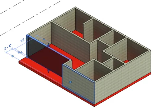
- From properties window, make sure top constrain is unconnected and change the unconnected height to 20’0” and press enter.
Step 2
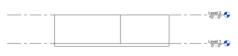
- For observing the difference between top constrain unconnected and top constrain up to level 2 go to the south view from the properties window which opens the south view as shown below.
Step 3
- Select the level 2 and click on heigh distance box of level 2 and edit it to 20’ it will change the heights all the walls that are set with top constrains up to level 2 along with the level line elevation as shown below.
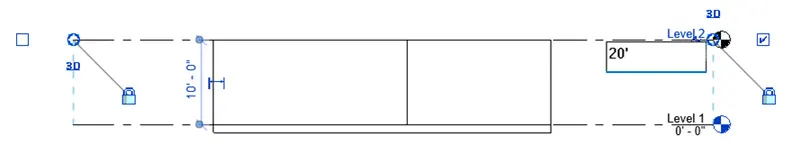
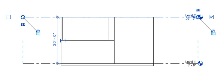
- The above steps show that when we set the top constrains of the wall up to level 2, the top constrains of the walls changes along with the level elevation, but if the wall top constrains kept unconnected then it will not changes along with the level elevations.
- So it is convenient and good practice of modelling to associate the walls with the level rather than being unconnected.
- Convenient option for modelling the wall between height or depth:
- When we select the depth option for drawing the wall it will show error that top of the wall is lower than base of the wall which cannot be ignored.
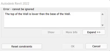
- Therefore for drawing the wall above the level, height is the convenient option for modelling the wall between height and depth as wall is always constructed above the level such as ground floor so that top of the wall is located above the level.
Result :
- Therefore, the walls are added according to the layout and materials are also applied to it and the output in the Revit software by using the above mentioned procedure is shown below.
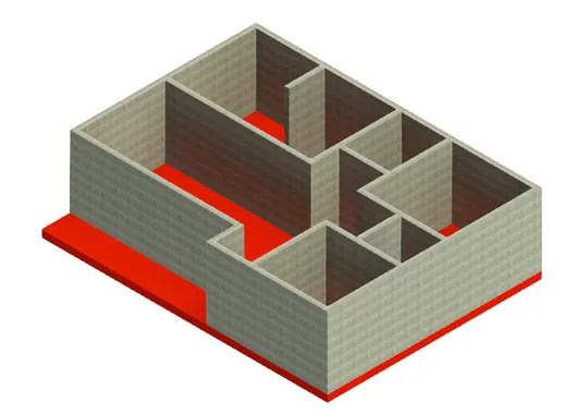
- From the above observation it is concluded that it is beneficial to connect the walls with associated level rather than being unconnected.
- Also it is observed that height is convenient option for modelling the walls instead of the depth.
3) Copy the model elements ( wall, floor ) modelled to Ground Floor Level and paste it aligned to First Floor Level . Use modify tab to utilize copy and paste options to align elements to a different level
Aim: To copy the model elements (walls, floor) model to ground floor level and paste it aligned to first floor level in Revit software.
Introduction :
- In Revit software we can copy the one floor level to its upper floor which minimizes the efforts of repeating the creation of same layout in upper floors and saves the considerable amount of time.
- Using the clipboard panel of modify tab we can copy the model elements from ground floor and paste it to the upper floors.
Procedure :
Step 1
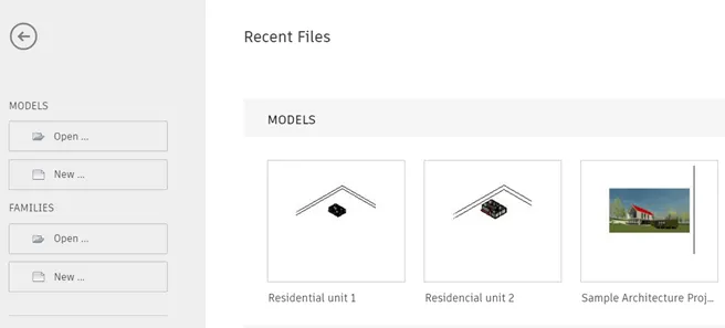
- Open the Revit software, select the Residential unit 1 and open it from home page of Revit software.
Step 2
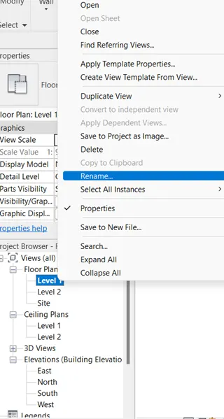
- Select the level option from the property browser and right click on it and select rename option to rename it as Ground Floor and press enter.
Step 3
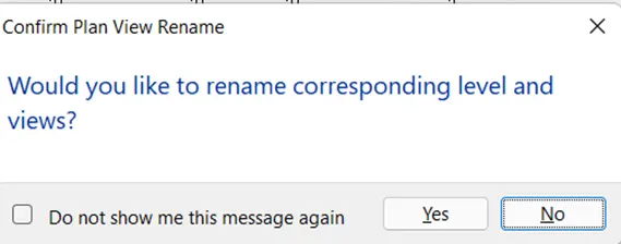
- Similarly rename the level 2 as First Floor by using the same procedure and select yes in the confirm plan view rename dialog box.
Step 4
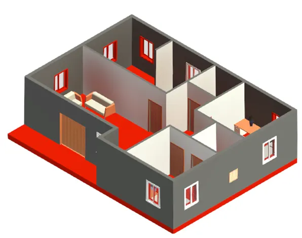
- From top toolbar select the default 3D view option to set the view as 3D view.
Step 5
- Select all components by dragging with mouse.
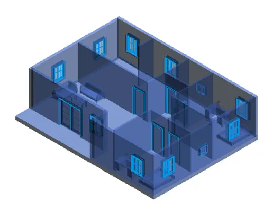
Step 6
- Select the copy to clipboard tool from clipboard panel of modify tab.

Step 7
- Select the paste tool dropdown and in that select aligned to selected Levels option.
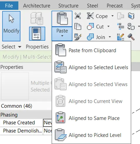
Step 8
- Select the level as First Floor level from select level dialog box and select ok.
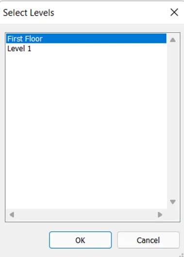
Step 9
- From top toolbar select the save option to save the changes in the file.
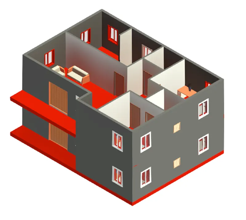
Result:
the output in the Revit software by following the above mentioned procedure is shown below.
3D realistic view of Revit mode
4) Use interior partition walls to create separate rooms within your residential unit. The model must include the following rooms
- Living Room/ Drawing Room ( 15’ X 18’)
b. Dining Room (9’ X 11’)
c. Bed Room ( 9’ X 12’ and 15’ X 11’)
d. Rest Room ( 10’ X 12’ )
e. Kitchen (8’ X 10’)
The above are for examples. You can use them or use your measured entities to create your model based on your layout. You may include entry walkway, Patios or Guest
rooms based on your creativity and purpose of modeling. Convert units if you are using metric system
Aim: To create model of residential unit in Revit software using partition walls to create separate room within residential unit.
Introduction:
- Revit is BIM software where we can model the residential units which includes walls, floors and other building components,
- In the model we can divide the available area into different regions to create them as separate room by using partition walls based on its purpose of utility.
Procedure:
Step 1
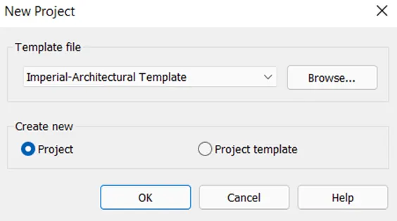
- Open the Revit, select new option from model menu, select the imperial architectural template as a template file and select ok.
Step 2
- Go to file menu, select save as option and save the project file naming as House 1
Step 3
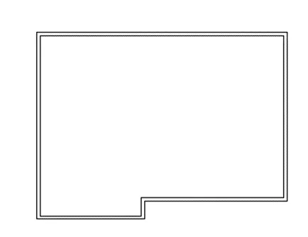
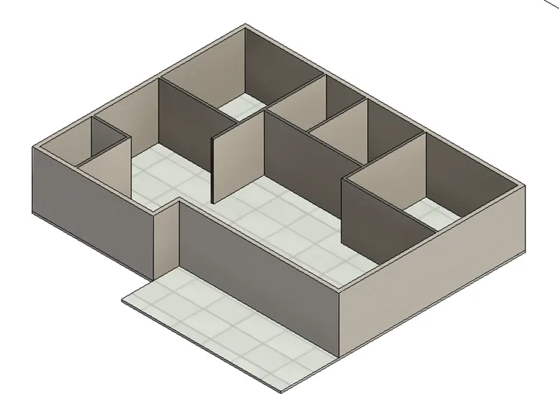
- Go to architecture tab, select wall tool from build panel, select line option from draw panel of modify wall tab, select the wall type as Generic – 8”, select the top constrains from wall up to level 2 and draw the exterior walls as per the layout of building as shown below.
Step 4
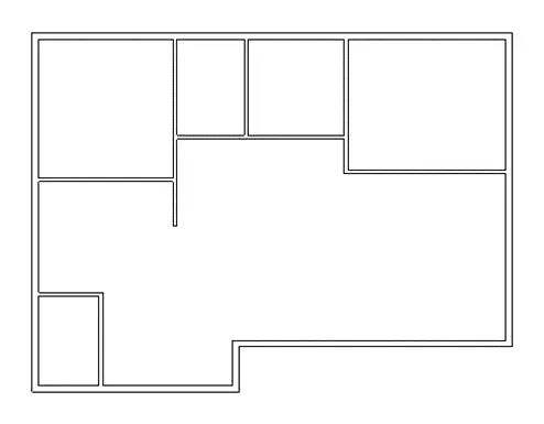
- Again, go to architecture tab, select the wall tool from build panel, select wall type as interior- partition 5” wall, select the top constrains of the wall as up to level 2, and draw the partition walls as per layout of plan as shown below.
Step 5
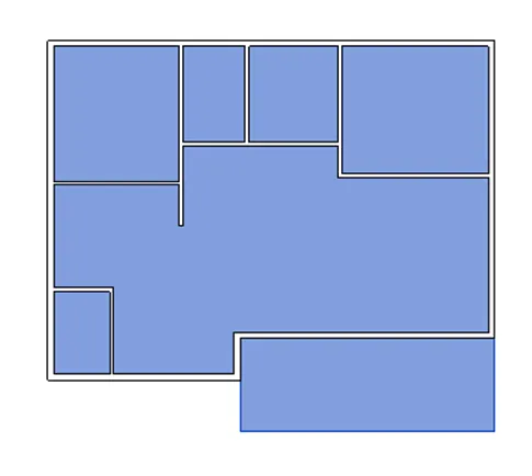
- Go to architecture tab, select the floor tool from build panel, select the pick line tool from draw panel, and draw the floor as per required layout as shown below.
Step 6
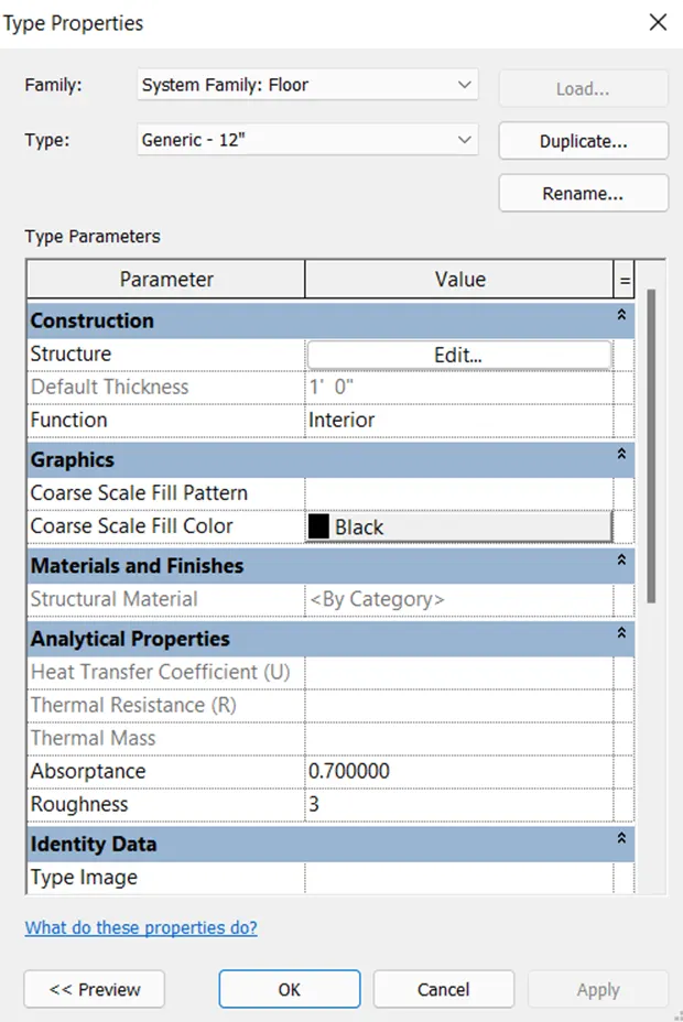
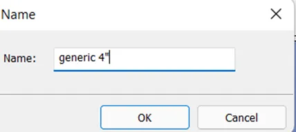
- For changing the material of the floor, select the floor, go to edit type from property window, select the duplicate option from type properties dialog box, change it as Generic 4”, select rename option and rename it as generic 4”.
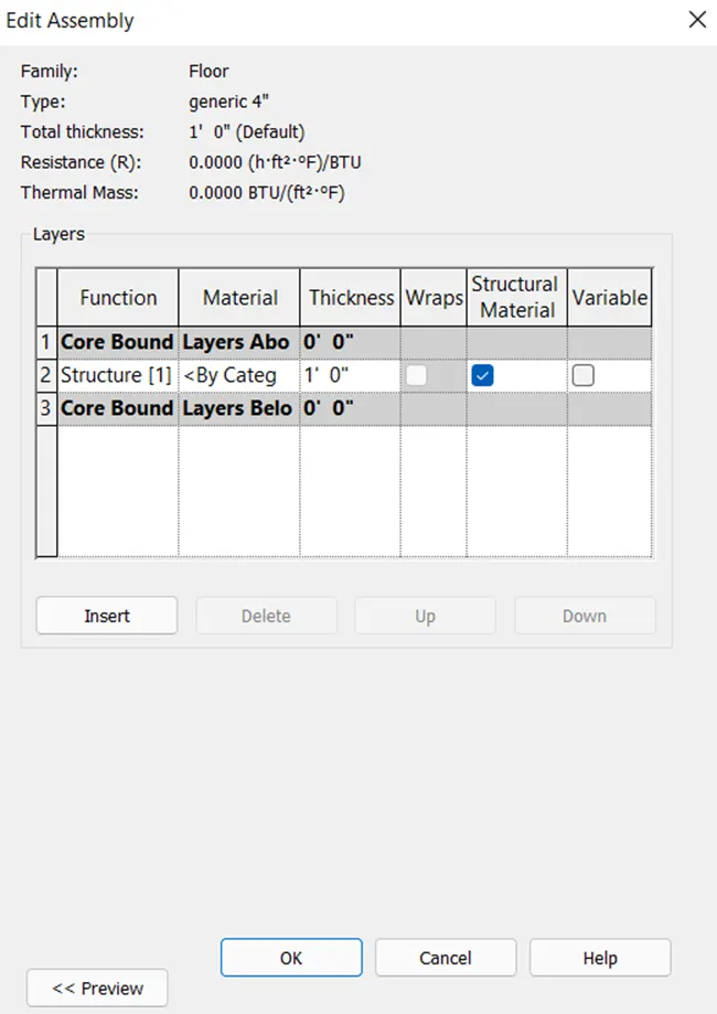
- Select edit option from type property dialog box it will open the edit assembly dialog box.
- Change the thickness of the floor to 4” and select the category option and edit the category as shown below to acoustic ceiling tile, select apply and select ok.
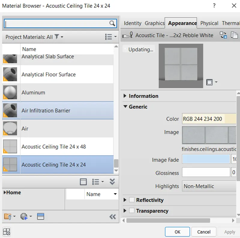
- Select apply option and select ok.
Step 7:
Similarly change the material of wall to brick common by similar way as that of flooring as shown below in 3D view.
Step 8
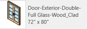
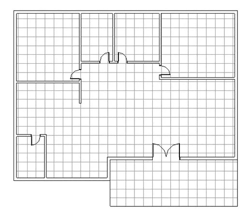
- To add doors and windows, go to floor plan of level 1 by double clicking on it, then go to architecture tab, select component from build panel, select load family from draw panel, select the door category, select the residential family, select type as door exterior double full glass wood clad of instance 72” x 80” and add it to the required position.
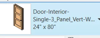
- Similarly add the door interior single 3 panel vert wood door at the required position as shown below.
Step 9
- Go to architecture tab, select window tool from build panel, select load family option from mode panel, select the windows category, select the window bow casement 10 degree type window, and add it to the required position.
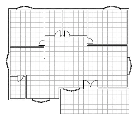
Step 10
- Similarly add the different components such as beds, chairs, desk, dining table, couch, coffee table, bathroom fixtures, kitchen cabinets, etc., using the similar components tools by using the appropriate category and family and add the in the model as shown below.
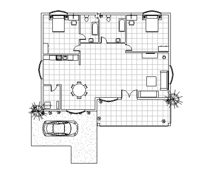
Result :
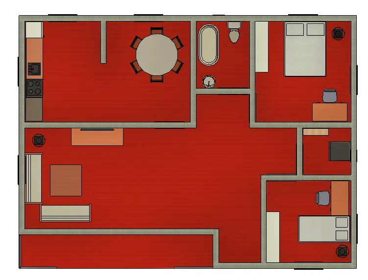
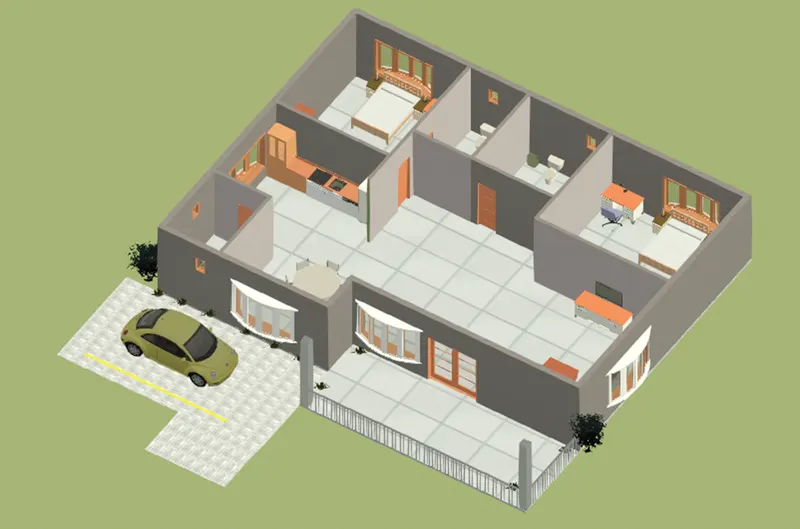
Therefore, the Revit model is created in Revit software by following the above mentioned procedure and the output in Revit software is shown below.
Ground floor plan
3D realistic view
5) Based on week 2 assignment, the components to be included in a residential unit were inserted to the Revit file. Place these components in appropriate locations to add details to your residential model
- Place Doors and windows in the wall at appropriate locations
b. The Living Room must include furniture set, couch table and TV desk and shelf cabinets
c. The Dining Room must include a table and chairs serving the purpose of eating
d. Bed Room must include a bed set, shelf, lighting and individual study desk and chair
e. Rest room should include bath tub and plumbing fixtures discussed in class
f. Kitchen should include countertops, gas stove cabinet and shelves to store food items
g. The wash/storage room can include washing machines and shelves to store clothes
All the components are available in Revit Library. Use them to place at appropriate locations to add details to your model. Use 3D navigation to check the model and its authenticity on a real time basis to verify the model
Aim : To add different components in the Revit model created in week 2 assignment which are available in Revit Library and use 3D navigation to check the model and its authenticity to verify the model in Revit software.
Introduction
- Revit is BIM software where we can add minute details so that we can make mode more virtual and realistic.
- We can add different components such as doors, window, beds, bathtub, washer etc.
Procedure :
Step 1
- Open Revit software and select the file naming as Residential unit 2 file to open it.
Step 2
- Go to architecture tab, select the door from build panel, select load family from mode panel it will open library dialog box.


- Select English-Imperial from dialog box and select open it will open the category dialog box as shown below.
Step 3
- Select the doors category and select open.
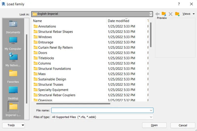
Step 4
- select the family as residential option from the dialog box, and select open.
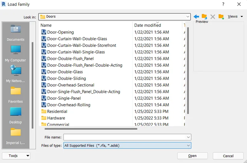
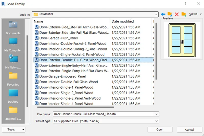
- Select the type as door exterior double full glass wood clad and select open.
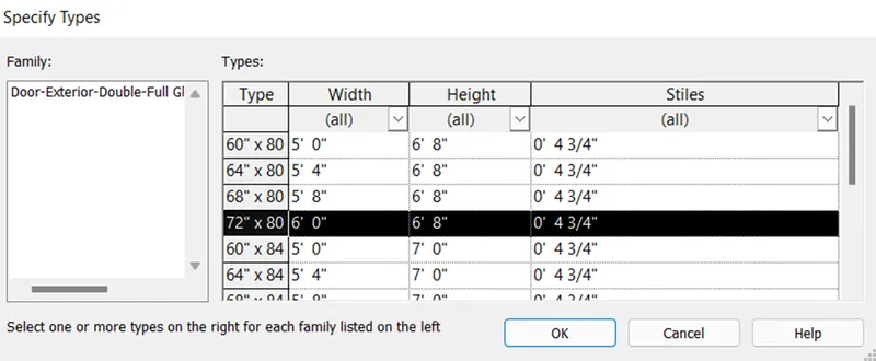
- Select the instance as 72’ x 80’ and select ok from specify types dialog box.
Step 4
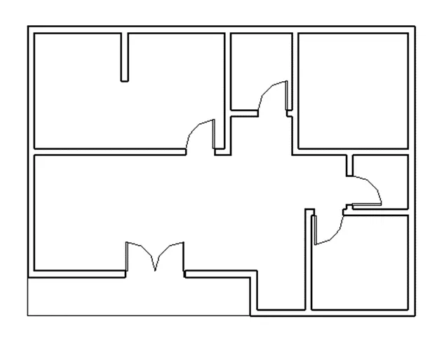
- Similarly create the other doors as single flush door using the same procedure as mentioned above as shown below.
Step 5
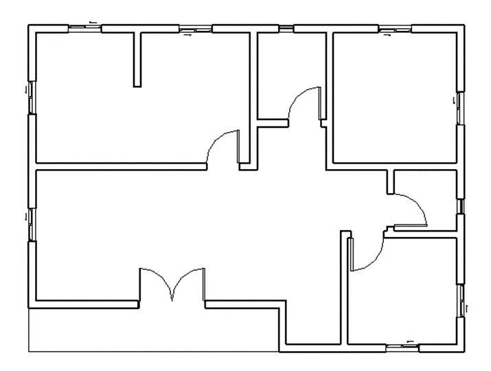
- Add window sliding double of size 36” x 48” by using similar procedure as mentioned for the door as shown below.
Step 6 : Living Room
- Go to architecture tab, select the component tool from build panel and select the load family.
- Select the category as furniture, family as seating, type as sofa and add the sofa in the living room at appropriate position as shown below.
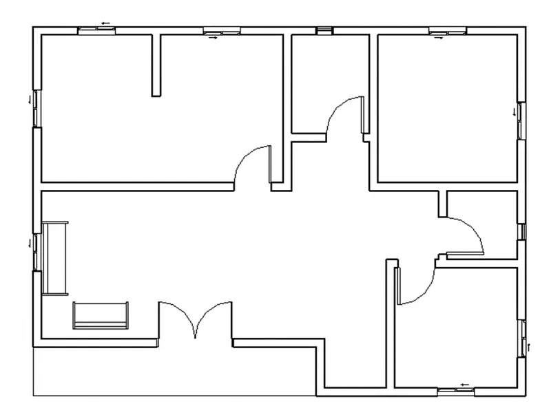
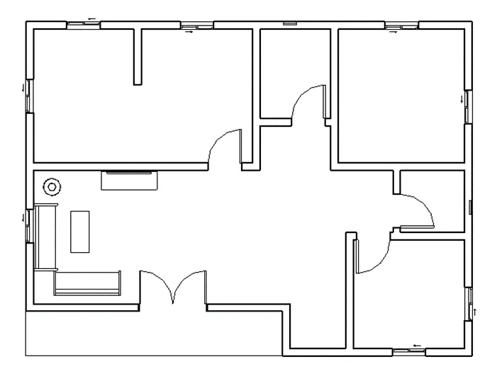
- Similarly for adding the tables, go to architecture tab, select component tool from build panel, select the load family from modify tab, select the furniture category, select the table family, select the type as coffee mission table and select open from dialog box to add the table and select the coffee mission table from property window and add the table in the living room.
- Similarly add the sideboard of size 60” in living room.
- To add television in the living room, go to Architecture
- For adding lamp, select the architecture tab, select component , place component option from build panel, select the load family, select lighting category, select the architectural, select the internal, select floor lamp standup and select open, go to property window and select added floor lamp and add it to required position.
Step 7 : creating of dinning room
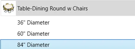
- For creating the dinning room, go to architecture tab, select the component tool from build panel, select the load family option from mode panel, select the furniture category from dialog box, select the table family, select the type as table dining with round and select open.
- From the property window select the dining table and add it to required position.
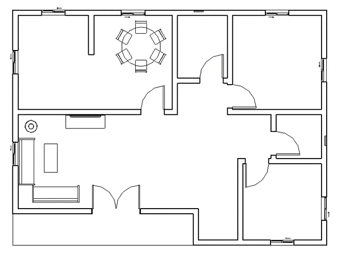
Step 8 : creating of the bedroom
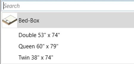
- Go to architecture tab, select component tool, select place component option, select load family option from mode panel, select the furniture category, select the beds family, select the bed box type and go to the property window and select the instance as 60” x 79” and add at the required position as shown below.
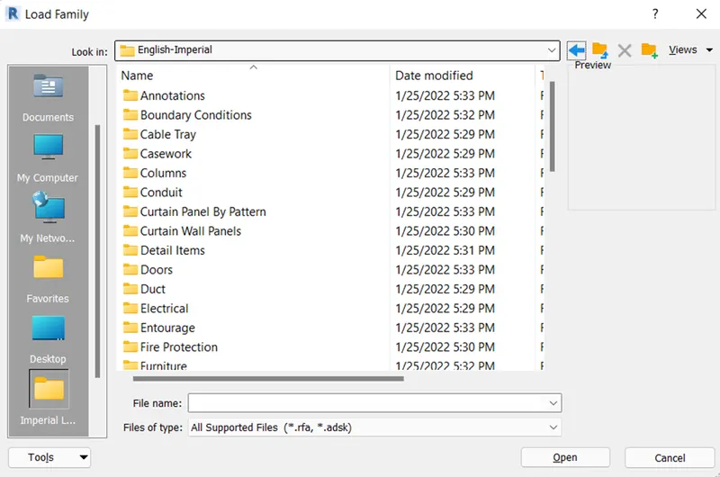
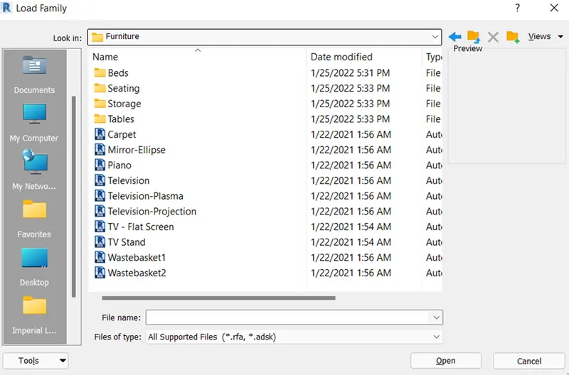
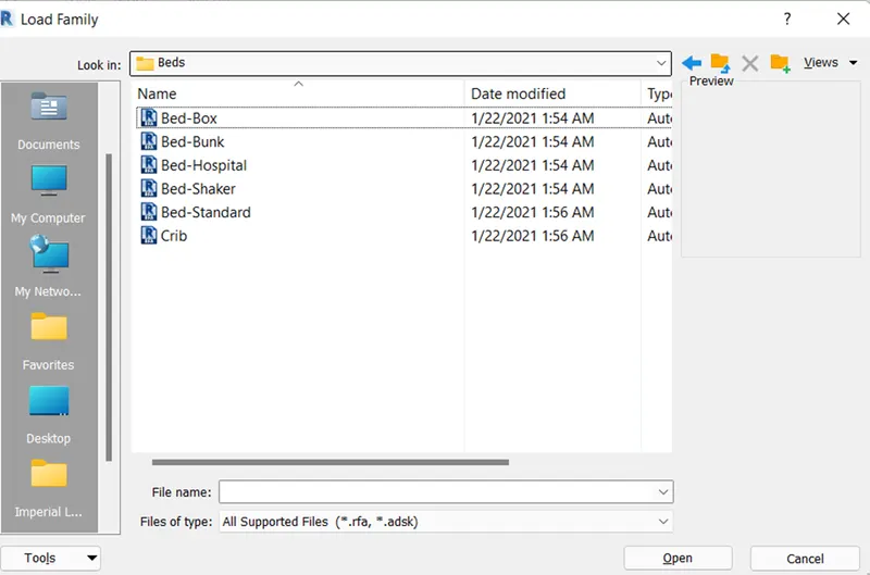
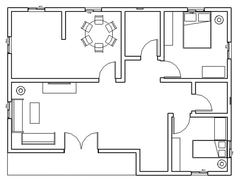
- Similarly load the desk table, of size 72” x 60” x 18” to properties window and then add at the required position.
- Also add the lamp and desk chair in the bedroom at the required position as shown below.
Step 9 : creating the kitchen
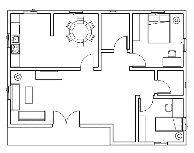
- Go to architecture tab, select the specialty equipment, select the domestic family, select type as kitchenette – medium type and add it to the property window.
- Select the added kitchen component type from property window, and add it to the required position.
- Similarly add Cabinet file lateral drawer from furniture category, storage type family as shown below.
Step 10 : creating the restroom
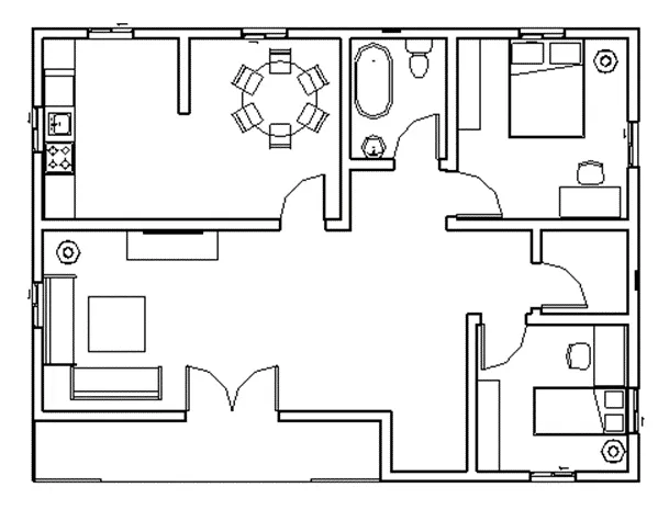
- Go to architecture tab, select component tool, select load family from mode panel, select plumbing as category, select architecture, select fixtures family, select type as bathtub, go to the property window, select bathtub and add in the restroom at the required position as shown below.
- Similarly add the toilet fixtures in the restroom as shown below.
Step 11 : Creating of the wash area
- Go to architecture tab, select component from build panel, select the load family from mode panel, select the specialty equipment, and select the residential family, select washer type and select open from dialog box.
- Go to property window, select washer from property window and add it to the required position.
- Similarly add the sleeve for cloths in the wash room from furniture category and storage family as shown below.
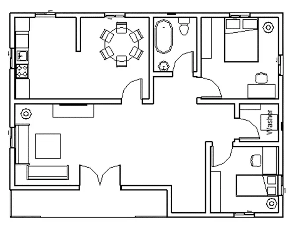
Result :
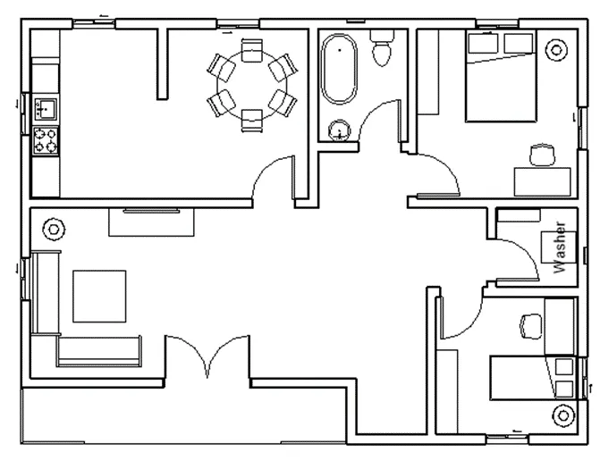
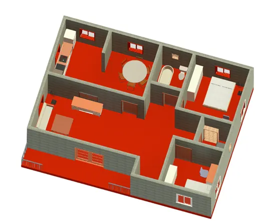
Different components are added in the Revit model using above mentioned procedure as shown below.
Plan view
3D view
Top right view using navigation view box
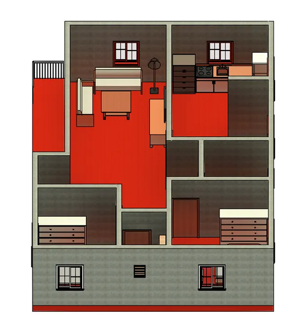
Top view in 3D