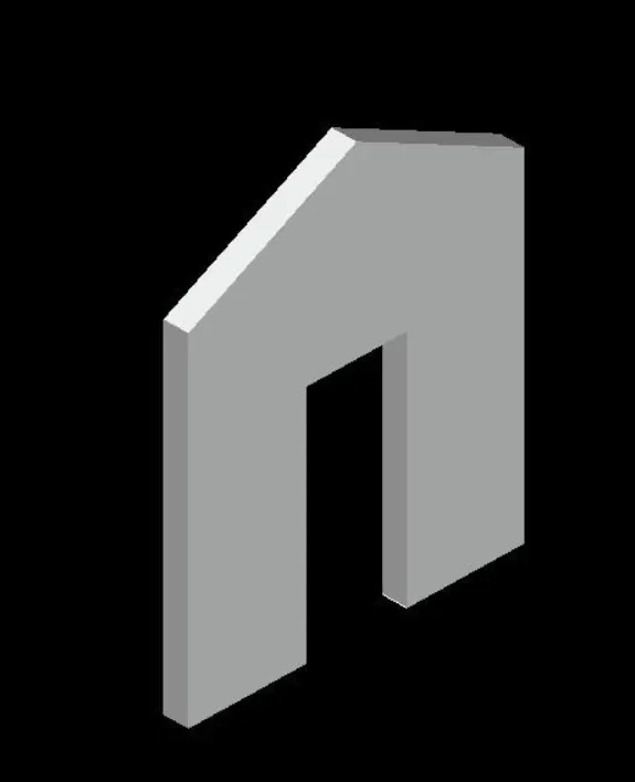
Creating various 3D Models like Furniture, Footing, Girder, Column drop with panel and Gable Wall in AutoCad
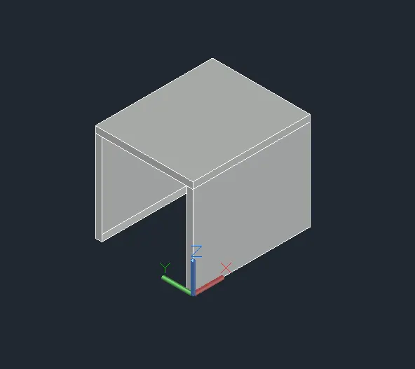
1. Create a 3D Furniture element as shown in the Figure. Assume dimensions which are missing.
- AIM:
To create 3D furniture element as shown in the figure.
- INTRODUCTION:
A 3D image is processed by 2D image by using 3D rendering from a special software.
It enchanes the profession creation and edition of 2D geomentry and 3D surface and solid blocks.
- PROCEDURE:
Create a new working sheet from application of Autocad.
Change the drafting to 3D modeling.
In command prompt type > units > Feet and inches.
In command prompt type > limits.
In command prompt type > rec of dimension required from 0,0 from Top view.
Now change to 3D custom view.
In command prompt type > 3Dorbit > parallel.
Then by using rectangular coordinates draw the required portions from 0,0,0.
Copy the rectangle to z axis of 2'6" (@0,0,2'6").
As per dimension in given figure proceed the method.
Extrude and offset the image, where ever it is required.
Then, from Wireframe to surface and to solid has to changed.
In command prompt type > 3dface to generate 3d faces.
By using hide command, hide all the lines which are bisected.
Now required 3d image is obtained.
- RESULT:
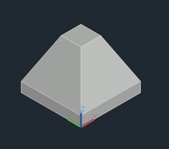
2. Create the 3d Model of an Isolated footing as shown in Figure.
- AIM:
To create 3d Model of an Isolated footing as shown in Figure.
- INTRODUCTION:
A 3D image is processed by 2D image by using 3D rendering from a special software.
It enchanes the profession creation and edition of 2D geomentry and 3D surface and solid blocks.
- PROCEDURE:
Create a new working sheet from application of Autocad.
Change the drafting to 3D modeling.
In command prompt type > units > Feet and inches.
In command prompt type > limits.
In command prompt type > rec of dimension required from 0,0 from Top view.
Now change to 3D custom view.
In command prompt type > 3Dorbit > parallel.
Then by using rectangular coordinates draw the required portions from 0,0,0.
Assume the footing rectangle as 3'x6".
As per dimension in given figure proceed the method.
Extrude and offset the image, where ever it is required.
Then, from Wireframe to surface and to solid has to changed.
In command prompt type > 3dface to generate 3d faces.
By using hide command, hide all the lines which are bisected.
Now required 3d image is obtained.
- RESULT:
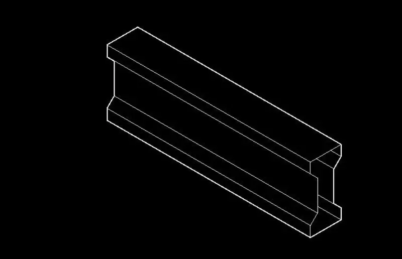
3. Create the 3D view of the AASTHO Type Girder.
- AIM:
To create the 3D view of the AASTHO Type Girder.
- INTRODUCTION:
A 3D image is processed by 2D image by using 3D rendering from a special software.
It enchanes the profession creation and edition of 2D geomentry and 3D surface and solid blocks.
- PROCEDURE:
Create a new working sheet from application of Autocad.
Change the drafting to 3D modeling.
In command prompt type > units > Feet and inches.
In command prompt type > limits.
Now change to 3D custom view.
In command prompt type > LINE of dimension required from 0,0,O.
The next point is (@1'6",0,0)
The next point is (@0,0,6")
The next point is (@6"<0<135) and do as per dimension required at all axis to complete the image.
In command prompt type > 3Dorbit > parallel.
As per dimension in given figure proceed the method.
Extrude and offset the image, where ever it is required.
Then, from Wireframe to surface and to solid has to changed.
In command prompt type > 3dface to generate 3d faces.
By using hide command, hide all the lines which are bisected.
Now required 3d image is obtained.
- RESULT:

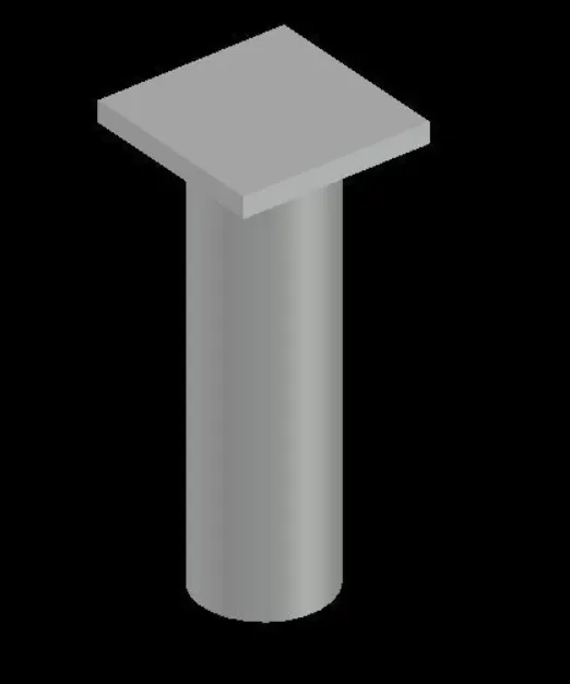
4. Create a 3d Model of a drop column with panel as shown in section and isometric view.
- AIM:
To create a 3d Model of a drop column with panel as shown in section and isometric view.
- INTRODUCTION:
A 3D image is processed by 2D image by using 3D rendering from a special software.
It enchanes the profession creation and edition of 2D geomentry and 3D surface and solid blocks.
- PROCEDURE:
Create a new working sheet from application of Autocad.
Change the drafting to 3D modeling.
In command prompt type > units > Feet and inches.
In command prompt type > limits.
In command prompt type > rec of dimension required from 0,0 from Top view.
Now change to 3D custom view.
In command prompt type > 3Dorbit > parallel.
Then by using rectangular coordinates draw the required portions from 0,0,0.
Assume the rectangle as 4'6".
Ttype c to create circle in command prompt.
Diameter of the circle is 1'6".
The column cap height is 1'.
The column head is 6" of thickness.
The height of the column is 10'.
As per dimension in given figure proceed the method.
Extrude and offset the image, where ever it is required.
Then, from Wireframe to surface and to solid has to changed.
In command prompt type > 3dface to generate 3d faces.
By using hide command, hide all the lines which are bisected.
Now required 3d image is obtained.
- RESULT:
5. Create the 3d model of a wall as shown in Figure. Consider wall thickness as 9”.
- AIM:
To create the 3d model of a wall as shown in Figure. Consider wall thickness as 9”.
- INTRODUCTION:
A 3D image is processed by 2D image by using 3D rendering from a special software.
It enchanes the profession creation and edition of 2D geomentry and 3D surface and solid blocks.
- PROCEDURE:
Create a new working sheet from application of Autocad.
Change the drafting to 3D modeling.
In command prompt type > units > Feet and inches.
In command prompt type > limits.
In command prompt type > line of dimension required from 0,0 from Top view.
Wall thickness is 9".
Fix door and its opening as per dimension given.
Now change to 3D custom view.
In command prompt type > 3Dorbit > parallel.
As per dimension in given figure proceed the method.
Extrude and offset the image, where ever it is required.
The extruded wall height is 10'.
Then, from Wireframe to surface and to solid has to changed.
In command prompt type > 3dface to generate 3d faces.
By using hide command, hide all the lines which are bisected.
Now required 3d image is obtained.
- RESULT: