Creating various 3D Models like Furniture, Footing, Girder, Column drop with panel and Gable Wall in AutoCad
AIM:
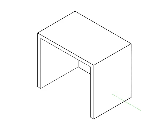
1. Create a 3D Furniture element as shown in the Figure. Assume dimensions which are missing.
2. Create the 3d Model of an Isolated footing as shown in Figure.
3. Create the 3D view of the AASTHO Type Girder.
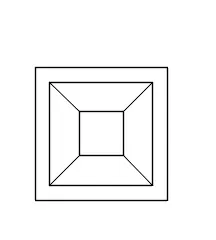
4. Create a 3d Model of a drop column with panel as shown in section and isometric view.
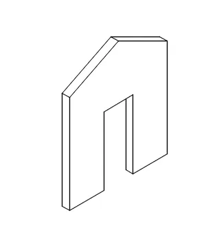
5. Create the 3d model of a wall as shown in Figure. Consider wall thickness as 9”.
PROCEDURE:
1. Open a drawing in 3d basics . select the ucs system and keep ortho on .
give command line and draw a line of 3'in negative y direction then 2'(assumend dimension) in negative x direction and then 3' in y direction and 2' in x direction then in -z direction draw aline of 2'6" then in y direction 2' and then in z direction 2'6" similarly from the other corner draw a line of 2'6" in -z direction and in y direction 2' then in z direction 2'6".
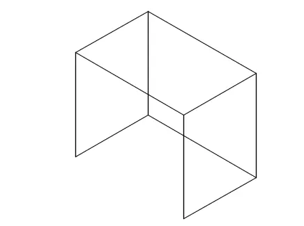
now from the left lower corner of the rectangle in xz frame draw aline in -y direction of 2" and then in z direction of 2'4" then in x direction of 2' then in -z direction of 2'-4" and then in -x direction 2' then press enter.
now from the left lower corner of the second rectangle in xz frame draw aline in y direction of 2" and then in z direction of 2'4" then in x direction of 2' then in -z direction of 2'-4" and then in -x direction 2' then press enter.
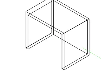
now give the command 3d face to hide the wireframe and one by one select all the faces of the figure by picking four points.
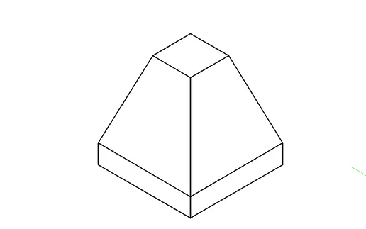
2. Select top view and draw a rectangle at any point and give the other point corner as @1',1'
then offset through any point (assumed dimension ) then go to the wcs view and select the rectamgle of @1',1' and move it in the z axis by distance @0,0,2' and then join the vertexes
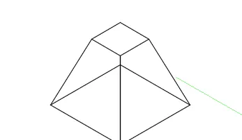
then select the offseted rectangle (assumed) dimension and copy it and move it -z direction by6" and join all the edges
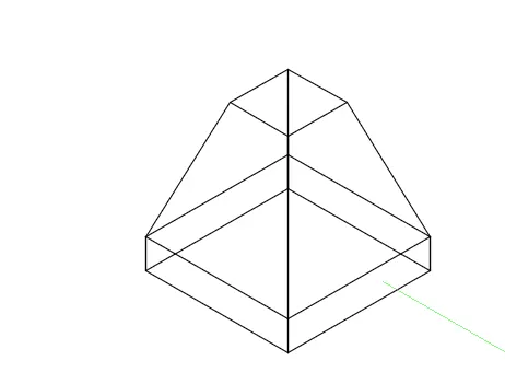
then give the 3dface command select all the face and then give hide command
3. Go to the front view
Command: l
LINE
Specify first point:
Specify next point or [Undo]: 1'
Specify next point or [Undo]: @0,0,-6"
Specify next point or [Close/Undo]: @-3,0,0
Specify next point or [Close/Undo]: @0,0,-1'6"
Specify next point or [Close/Undo]: @6",0,-6"
Specify next point or [Close/Undo]: @0,0,-6"
Specify next point or [Close/Undo]: @-1'6",0,0
Specify next point or [Close/Undo]: @0,0,6"
Specify next point or [Close/Undo]: @6",0,6"
Specify next point or [Close/Undo]: @0,0,1'6"
Specify next point or [Close/Undo]: @-3",0,0
Specify next point or [Close/Undo]: c
command: l
Specify first point: select the left bottom corner
Specify next point or [Undo]: @1",0,-1"
Specify next point or [Undo]: 1'4"
Specify next point or [Close/Undo]: @1"0,1"
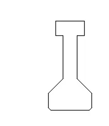
now go to the wcs view make the figure region. by region command
now give the extrude command select mode solid. and give height in the y direction as 10'
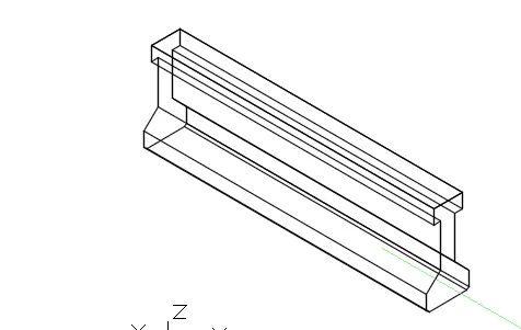
now give the 3d face command and select the face pf the figure
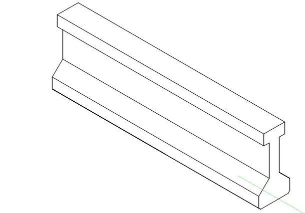
4. Select front view and draw a square or polygon of sides 4
and radius 2'3" and then draw another square of radius 1'9" and one more of 9".
then go to front wcs view and select the square of radius 9" and move it 1' in -z direction and then draw the vertex or join the sides of radius 9" polygon and and radius 1'9" polygon.
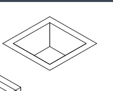
then again go to front view and give command cylinder select the center of 9" radius polygon as the center of the cylinder give radius 9" and height as -10'
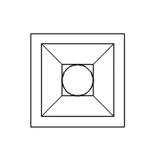
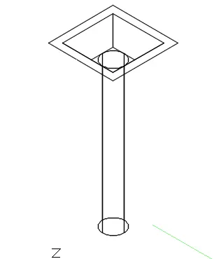
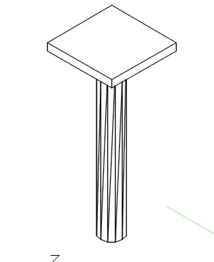
then give command extrude and select object the square of radius 2'3" and give height as 6"
and then give hide command.
5.Select the front view assume size of the wall 10'
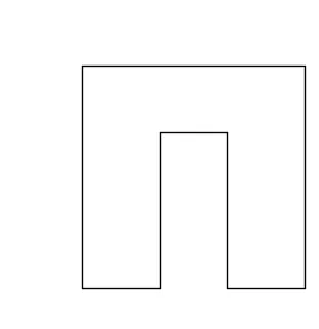
Command: _line
Specify first point: anywhere
Specify next point or [Undo]: @0,0,10'
Specify next point or [Undo]: @10',0,0
Specify next point or [Close/Undo]: @0,0,-10'
Specify next point or [Close/Undo]: @-3'6",0,0
Specify next point or [Close/Undo]: @0,0,7'
Specify next point or [Close/Undo]: @-3',0,0
Specify next point or [Close/Undo]: @0,0,-7'
Specify next point or [Close/Undo]: c
then
Command: l
LINE
Specify first point: midpoint of the top line by object snap
Specify next point or [Undo]: @0,0,2.5'
Specify next point or [Undo]: the end point of top line (left)
Specify next point or [Close/Undo]: *Cancel*
Command: l
LINE
Specify first point: the top of the line drawn from midpoint.
Specify next point or [Undo]: the end point of the top line (right)
Specify next point or [Undo]: *Cancel*
Command: e
ERASE 2 found erase the top line and the top of the line drawn from midpoint.
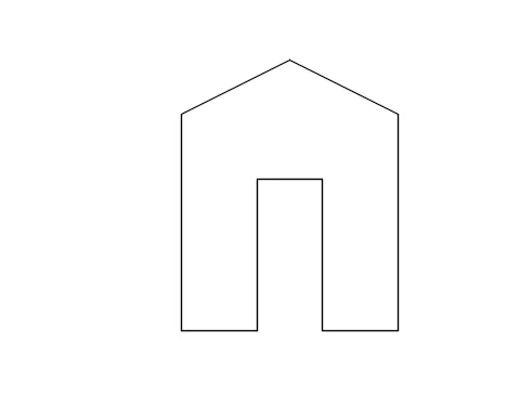
now go to the wcs view and select the figure and give region command and make it a region.
then give extrude command select mode solid and give height 9" and give hide command.
RESULT:
1.
2.
3.
4.
5.