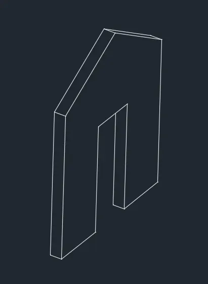
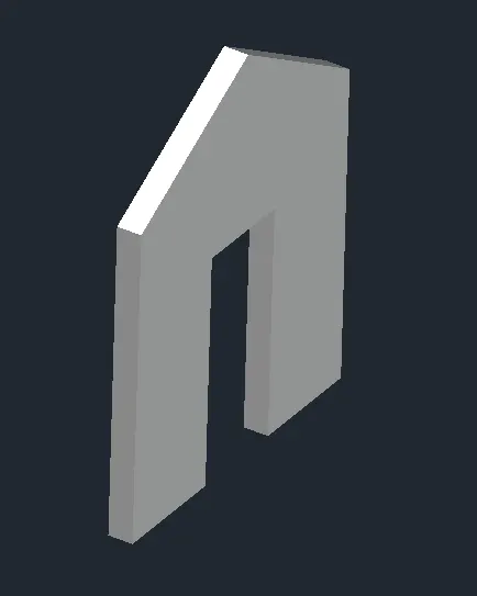
Creating various 3D Models like Furniture, Footing, Girder, Column drop with panel and Gable Wall in AutoCad
Q1: Aim: To Create a 3D Furniture element and illustrate the procedure involved.
Procedure:
- Create a new drawing from the dropdown menu
- Select the imperial system and Engineering units
- Type LIMMAX and set limits 100",100"
- Select 2D wireframe
- Type L and select the starting point
- Position the cursor and type the distance 30"
- Position the cursor and type the distance 36"
- Position the cursor and type the distance 30"
- Position the cursor and type the distance 2"
- Position the cursor and type the distance 28"
- Position the cursor and type the distance 32"
- Position the cursor and type the distance 28"
- Position the cursor and type the distance 2"
- Type REGION and select the object press enter
- Type EXT and select the object, press enter
- Type height od extrusion 18"
- Type HIDE and press enter
- Save the drawing
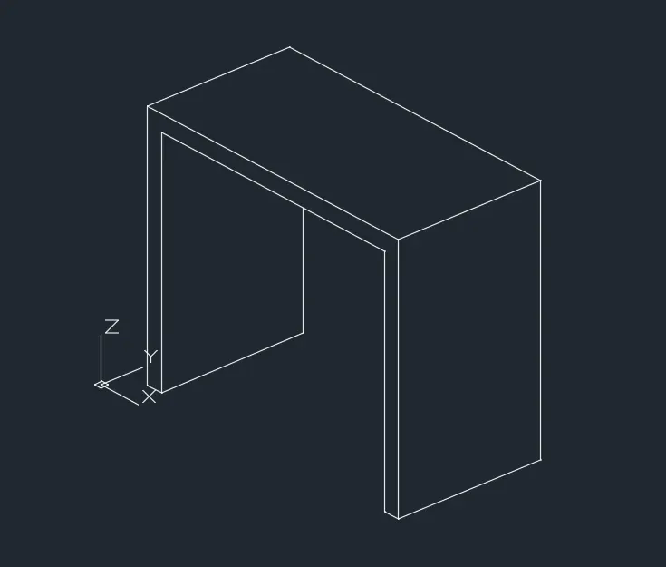
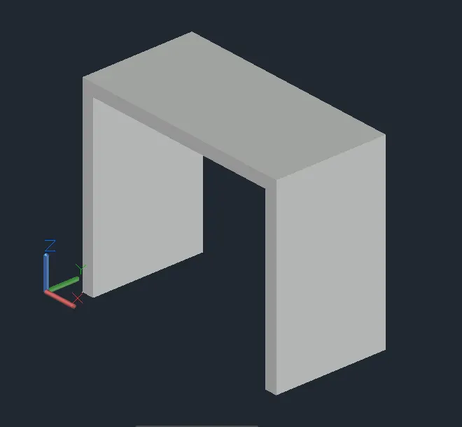
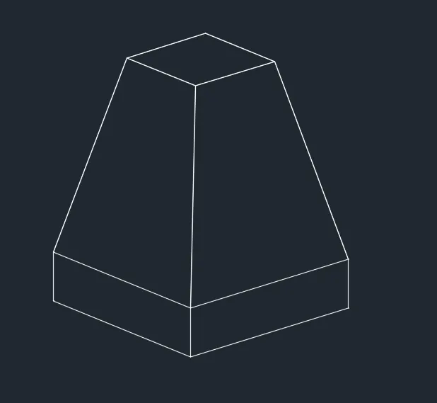
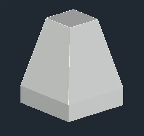
Q2: Aim: To Create a 3D model of an isolated footing and illustrate the procedure involved.
Procedure:
- Create a new drawing from the dropdown menu
- Select the imperial system and Engineering units
- Type LIMMAX and set limits 100",100"
- Select 2D wireframe
- Type REC and select the first point
- Select dimension and give dimension 2' x 2'
- Type O and give offset distance of 6" and create an inner rectangle
- Type M and select the smaller rectangle and press enter
- Select the base point on the smaller rectangle and enter the distance 2'6"
- Type REGION and select the 2' x 2' rectangle to create a region
- Type EXT and select the 2' x 2' rectangle press enter
- Type height of extrusion 6"
- Join the corners of the 1' x 1' rectangle with the extruded solid model using the L command
- Type 3F and select the 4 corners of each side to convert it to surface
- Type HIDE and press enter
- Save the drawing
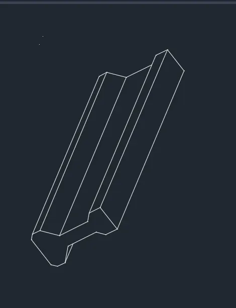
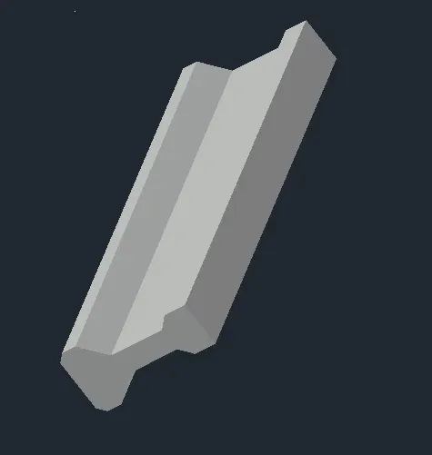
Q3: Aim: To Create the 3D view of the AASTHO Type Girder and illustrate the procedure involved.
Procedure:
- Create a new drawing from the dropdown menu
- Select the imperial system and Engineering units
- Type LIMMAX and set limits 100",100"
- Select 2D wireframe
- Type REC and select the first point
- Select dimension and give dimension 1'6" x 1'
- Type EXPLODE and select the rectangle and press enter
- Type CHA and select the distance option
- Type the first and second distance as 2" and chamfer the bottom edges of the rectangle
- Type CHA and select the distance option
- Type the first and second distance as 6" and chamfer the top edges of the rectangle
- Type L and select the top-left edge as the first point
- Position the cursor and type the distance 1'3"
- Position the cursor and type the distance 3"
- Position the cursor and type the distance 9"
- Position the cursor and type the distance 1'
- Position the cursor and type the distance 9"
- Position the cursor and type the distance 3"
- Position the cursor and type the distance 1'3"
- Type TR and trim the extra line
- Type CHA select the distance option
- Type the first and second distance as 3" and chamfer the bottom edges of the top rectangle
- Type REGION and select the object to create a region
- Type EXT and select the object press enter
- Type height of extrusion 10'
- Type HIDE and press enter
- Save the drawing
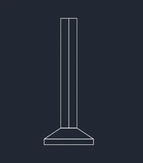
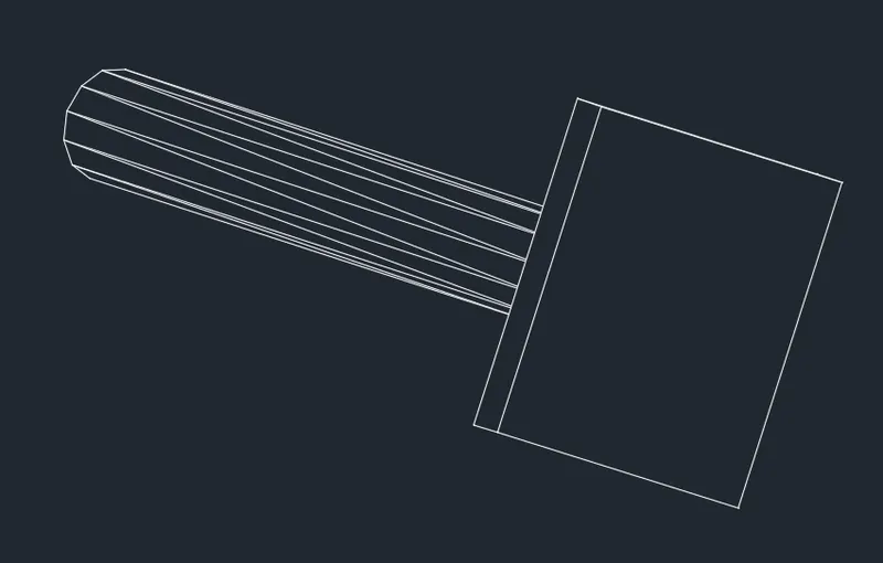
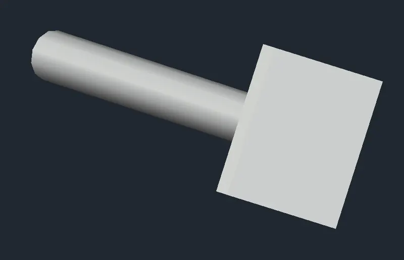
Q4: Aim: To Create a 3d Model of a drop column with a panel and illustrate the procedure involved.
Procedure:
- Create a new drawing from the dropdown menu
- Select the imperial system and Engineering units
- Type LIMMAX and set limits 100",100"
- Select 2D wireframe
- Type REC and select the first point
- Select the dimension and give dimension 4'6"
- Type O and enter distance 1'6"
- Offset the rectangle
- Type C and select the diameter option
- Enter diameter 1'6" and press enter
- type M and select the circle and 1'6" x 1'6" rectangle
- Position the cursor and enter distance 1'6"
- Type REG and select the 4'6" x 4'6" rectangle and press enter, repeat the same procedure for the other rectangle and circle also
- Type EXT and select the 4'6" x 4'6" rectangle
- Position the cursor and enter the height of extrusion 6"
- Join the corners of the two rectangles using the line command
- Type 3F and select the 4 corners of each side to convert it to surface
- Type EXT and select the circle
- Position the cursor and enter the height of extrusion 10'
- Type HIDE and press enter
- Save the drawing
Q5: Aim: To Create the 3d model of a wall and illustrate the procedure involved.
Procedure:
- Create a new drawing from the dropdown menu
- Select the imperial system and Engineering units
- Type LIMMAX and set limits 100",100"
- Select 2D wireframe
- Type REC and select the first point
- Select dimension and give dimension 10' x 12'6"
- Type EXPLODE and select the rectangle and press enter
- Type REC and select the first point
- Select the dimension and give dimension 3' x 7'
- Align this rectangle with the centre of the bottom line of the bigger rectangle
- Type O and enter 3' as the offset distance
- Type L and draw a triangle joining the centre point of the top line and endpoints of the new line.
- Type TR and trim the extra lines
- Type REG and select the object to form a region
- Type EXT and select the object
- Position the cursor and enter the height of extrusion 9"
- Type 3DROTAE and rotate the object into the correct orientation
- Type HIDE and press enter
- Save the drawing