Creating various 3D Models like Furniture, Footing, Girder, Column drop with panel and Gable Wall in AutoCad
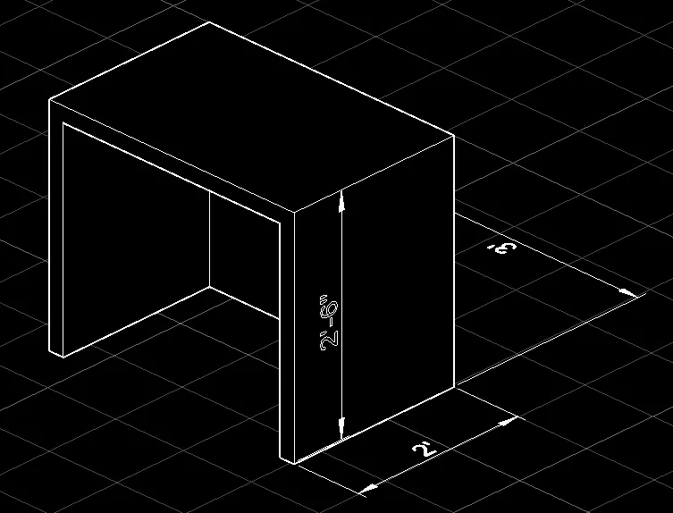
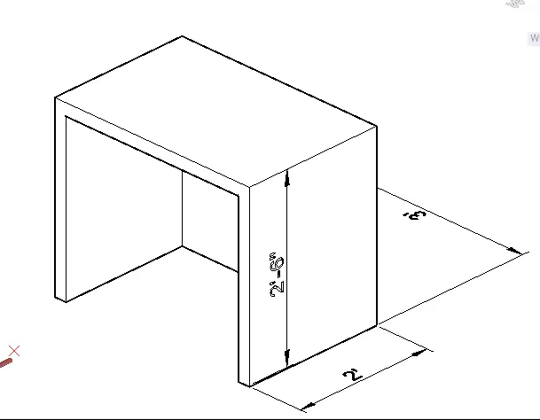
Q1. Create a 3D Furniture element as shown in the Figure. Assume dimensions which are missing.
AIM: To create a 3D furniture element as shown in the figure
PROCEDURE:
- Open AutoCAD and set to 3d modeling
- In command prompt type UNITS, set to Architecture and precision = 0'-0", Insertion scale as Inches
- In command prompt type LIMAX, set to 100,100
- In command prompt type LIMITS, set to 0,0
- In command prompt type Zoom, select all, and enter
- In command prompt type REC, specify dimensions length, width as 2',3' in plan view

- In command prompt type EXT, extrude the created rectangle to 2'-6" in an upward direction in 3d view
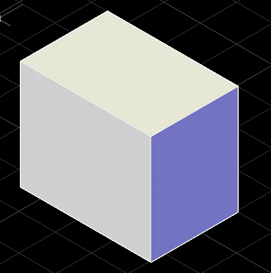
- In command prompt type REC, draw the inner rectangle, and extrude to the inner side
- In command prompt type SUB, select the inner object, and subtract it
- In the Ribbon bar from Annotate tab dimensions panel is used to assign required dimensions
CONCEPTUAL VIEW
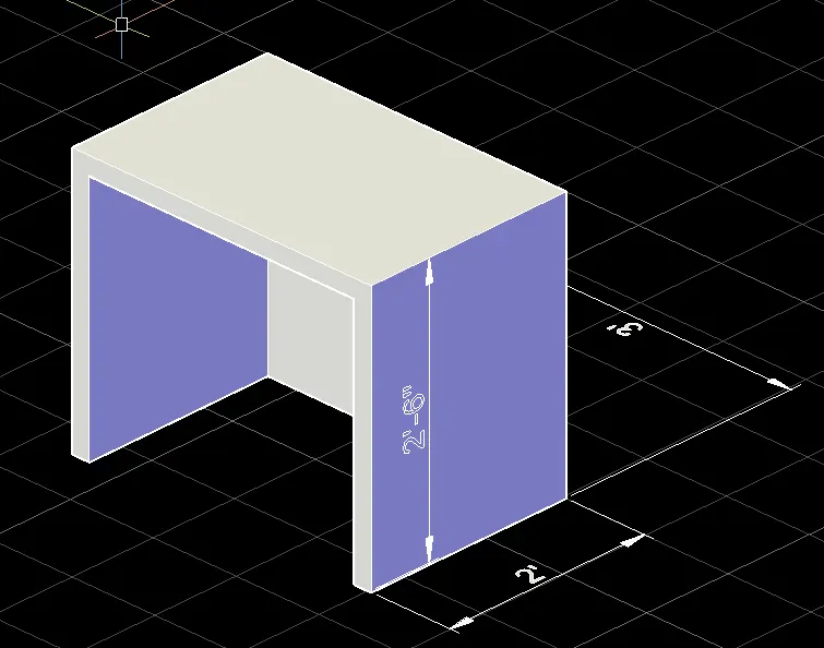
RESULT:
2D WIREFRAME VIEW LAYOUT VIEW
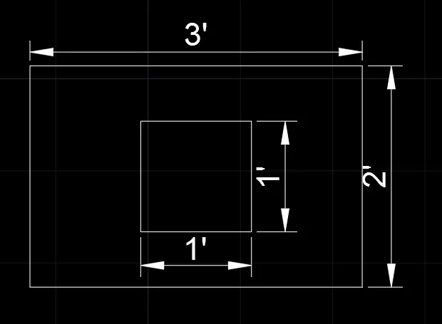
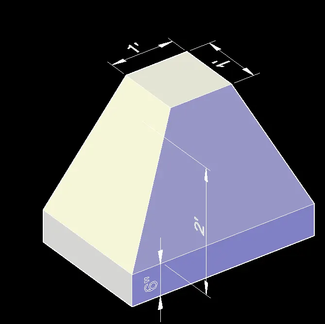
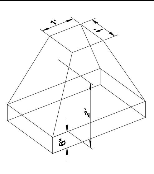
Q2. Create the 3d Model of an Isolated footing as shown in Figure.
AIM: To create the 3D model of isolated footing as shown in figure
PROCEDURE:
- Open AutoCAD and set to 3d modeling
- In command prompt type UNITS, set to Architecture and precision = 0'-0", Insertion scale as Inches
- In command prompt type LIMAX, set to 100,100
- In command prompt type LIMITS, set to 0,0
- In command prompt type Zoom, select all, and enter
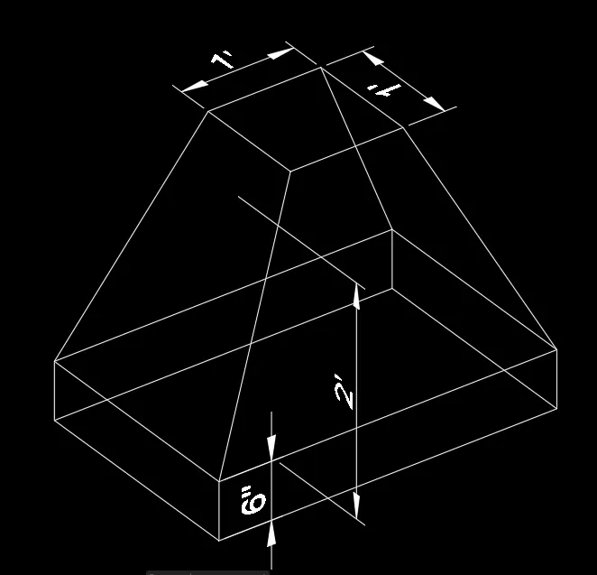
- In command prompt type REC, create rectangle 3',2' and 1',1'
- In command prompt type 3DMOVE, move the smaller rectangle in z+ direction of 2'
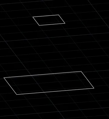
- In command prompt type EXTRUDE, extrude the bigger rectangle by 6"
- In command prompt type LINE, join the smaller rectangle with bigger one
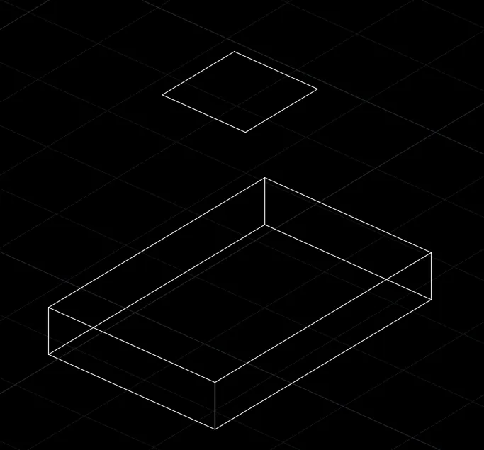
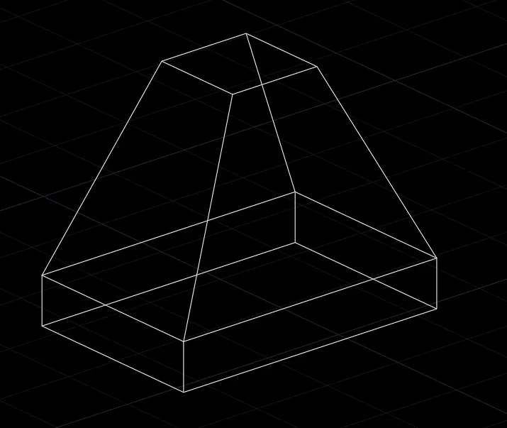
- In command prompt type 3DFACE, select the points to get faces to do where ever required
- In the Ribbon bar from Annotate tab dimensions panel is used to assign required dimensions
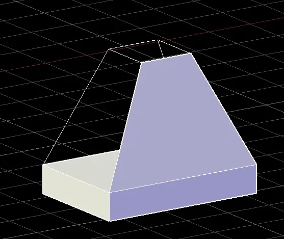
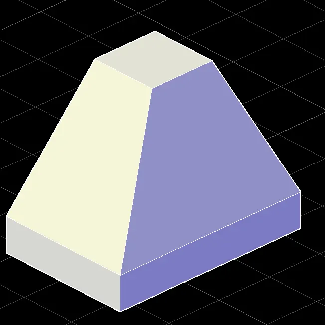
RESULT:
2D WIREFRAME VIEW CONCEPTUAL VIEW
LAYOUT VIEW
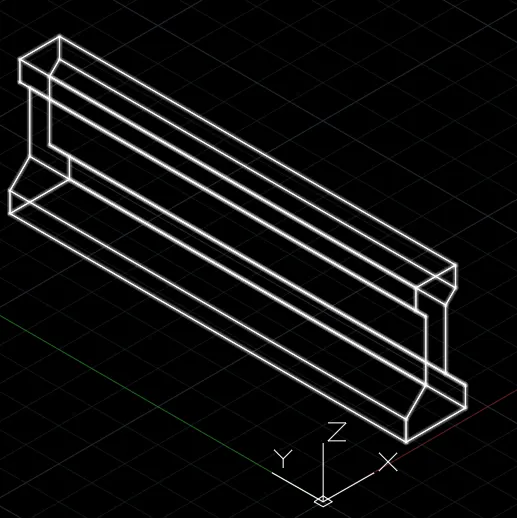
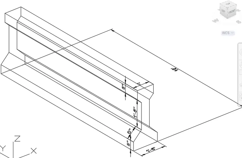
Q3. Create the 3D view of the AASTHO Type Girder.
AIM: To create 3D view of AASTHO type grider
PROCEDURE:
- Open AutoCAD and set to 3d modeling
- In command prompt type UNITS, set to Architecture and precision = 0'-0", Insertion scale as Inches
- In command prompt type LIMAX, set to 100,100
- In command prompt type LIMITS, set to 0,0
- In command prompt type Zoom, select all, and enter
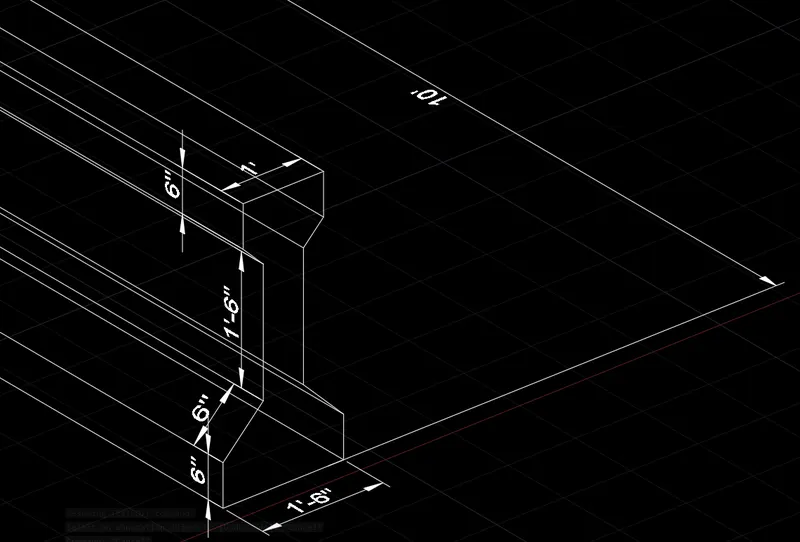
- In command prompt type LINE, make lines to get I-section as 1'-6",6",1-6",6",1'
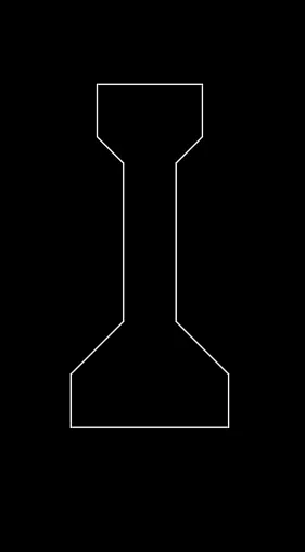
- In command prompt type 3DROTAE, rotate the I-section to angle 90 degree to get in front view

- In command prompt type LINE, specify the length as 10'
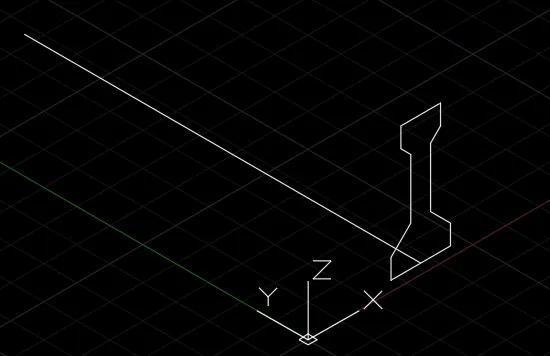
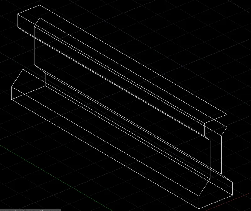
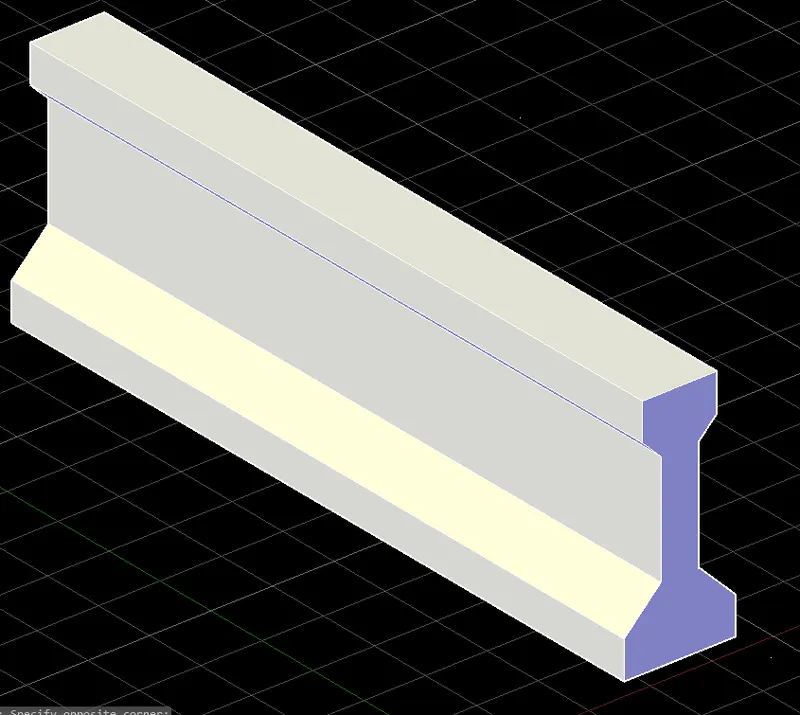
- In command prompt type SWEEP, select the object and path to sweep
- In the Ribbon bar from Annotate tab dimensions panel is used to assign required dimensions
RESULT:
2D WIREFRAME VIEW CONCEPTUAL VIEW
LAYOUT VIEW
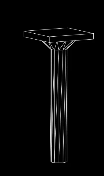
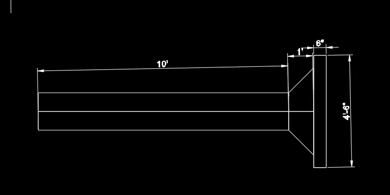
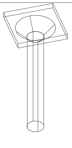
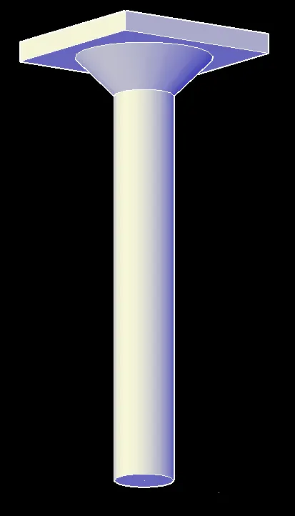
Q4. Create a 3d Model of a drop column with panel as shown in section and isometric view.
AIM: To create 3D model of drop column with panel
PROCEDURE:
- Open AutoCAD and set to 3d modeling
- In command prompt type UNITS, set to Architecture and precision = 0'-0", Insertion scale as Inches
- In command prompt type LIMAX, set to 100,100
- In command prompt type LIMITS, set to 0,0
- In command prompt type Zoom, select all, and enter
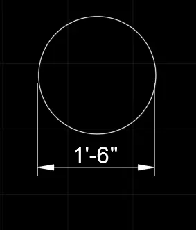
- In command prompt type CIRCLE, create circle with diameter of 1'-6" in top view
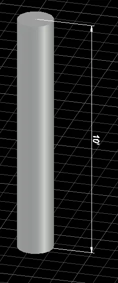
- In command prompt type EXTRUDE, extrude the circle created by 10'
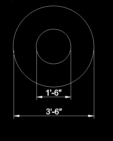
- In command prompt type CIRCLE, create concentric circles of diameters 1'-6" and 3'-6"
- In command prompt type 3DMOVE, move the bigger circle by 1' in z+ direction
- In command prompt type LOFT, select circles, and create the loft between them
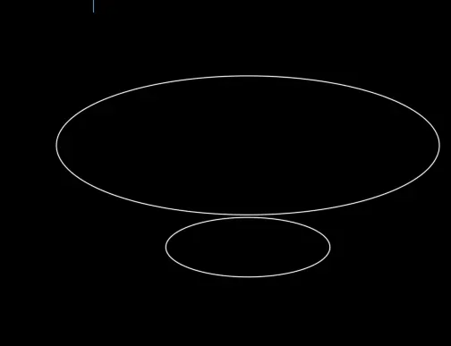
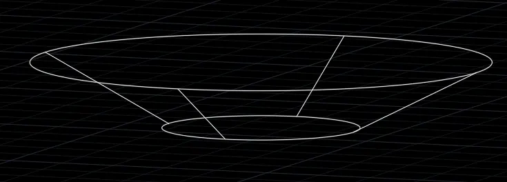
- In command prompt type move, select the created cone with move with the help of snap object and place it over the created at top of 10' rod
- In command prompt type REC, create rectangle with dimensions of length,width as 4'-6",4'-6"
- In command prompt type EXTRUDE, extrude the created rectangle by 6"
- In command prompt type MOVE, move the rectangle to top of the cone by the help of object snap
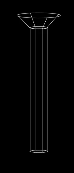
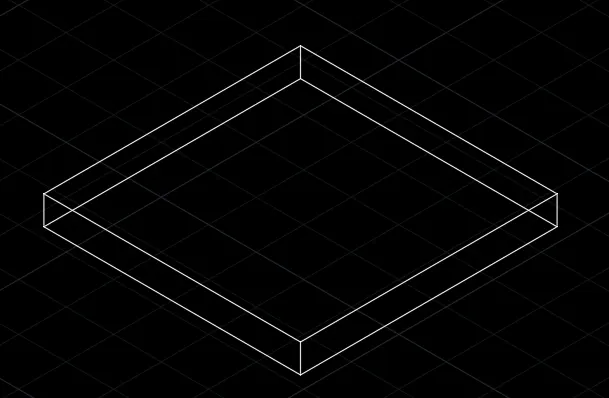
- In the Ribbon bar from Annotate tab dimensions panel is used to assign required dimensions
RESULT:
2D WIREFRAME VIEW / SECTION VIEW
LAYOUT VIEW ISOMETRIC VIEW
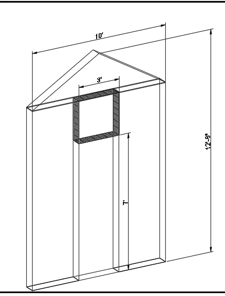
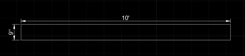
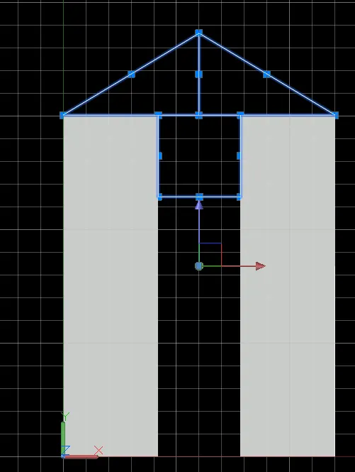
Q5. Create the 3d model of a wall as shown in Figure. Consider wall thickness as 9”.
AIM: To create 3D model of the wall having a thickness as 9" as shown in the figure
PROCEDURE:
- Open AutoCAD and set to 3d modeling
- In command prompt type UNITS, set to Architecture and precision = 0'-0", Insertion scale as Inches
- In command prompt type LIMAX, set to 100,100
- In command prompt type LIMITS, set to 0,0
- In command prompt type Zoom, select all, and enter
- In command prompt type REC, create a rectangle by length, width as 10',9"
- In command prompt type OFFSET, offset for door is created
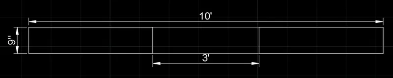
- In command prompt type BO, select the boundary region by pick points
- In command prompt type EXTRUDE, extrude the boundary region area
- In command prompt type UCS, create a view as desired, and make a line for slant wall
- In command prompt type EXTRUDE, extrude the slant wall
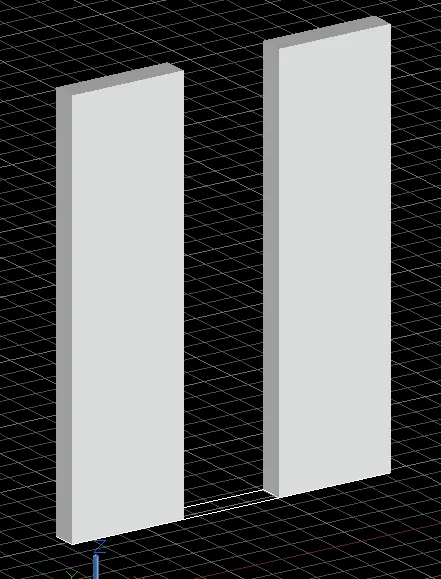
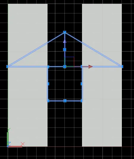
- In the Ribbon bar from Annotate tab dimensions panel is used to assign required dimensions
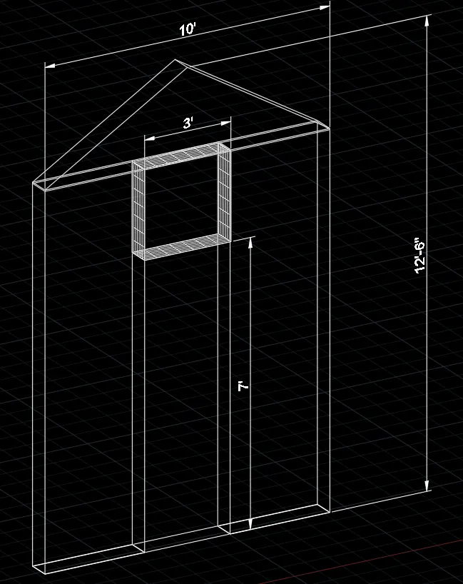
RESULT:
2D WIREFRAME VIEW CONCEPTUAL VIEW
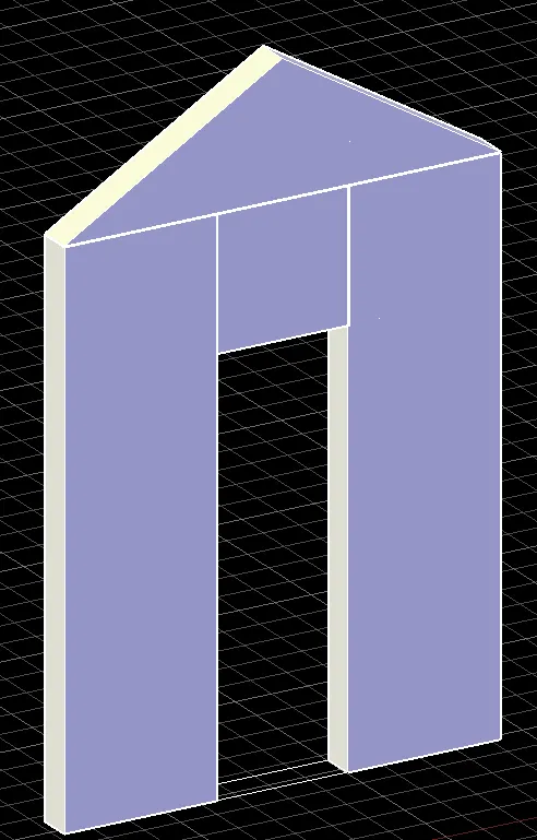
LAYOUT VIEW