Creating various 3D Models like Furniture, Footing, Girder, Column drop with panel and Gable Wall in AutoCad
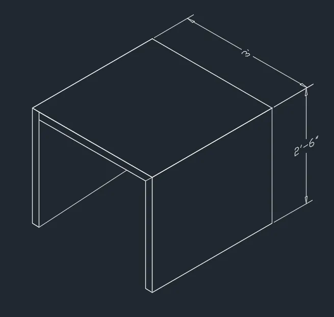
1. Creating a Small Furniture Element in Three-Dimensional Layout to Showcase its Surface Features.
STEPWISE PROCEDURE:
- Create a rectangle of the size 3'x3' in the XY-3D plane.
- Extrude the same rectangle in the negative Z-plane.
- While extruding the object, give the extrusion height as -2'-6".
- Give an offset of 6" inches at the front of the box created.
- Use the line command to lay down the opening of the furniture.
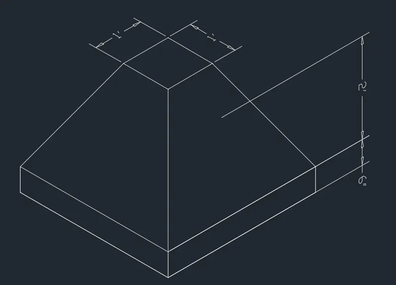
2. Creating the 3D Model of an Isolated Footing with the Predefined dimensions in the Trapezoidal Shape.
STEPWISE PROCEDURE:
- Create a rectangle of the size 1'x1' in XY-3D plane.
- Use the region command, select the object and make it a surface.
- Then, make use of the extrude command and select the object to extrude that is the previously created rectangle.
- While extruding the rectangle, give the extrusion height as 2'.
- Also, select the tapered angle option within extrude command and give the tapered angle of negative30 degrees.
- Then, use the line command and create the foundation of the overall depth of 6 inches.
- Create the surface using the "3F" command.
- Then use the union command to make the entire isolated footing as a single entity.
- At last, use the hide command to display the outlook of the isolated footing.
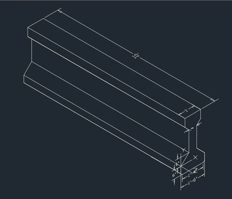
3. Creating the AASHTO (American Association of State Highways and Transportation Officials) Standard Girder.
STEPWISE PROCEDURE:
- Change the custom view to the top view from the top left corner of the screen.
- Use the Line command to create the front view of the AASHTO girder.
- Give the Accurate standard sizes of different components of the girder in the front elevation.
- Shift back to the 3d modeling by clicking on the home icon on the view cube.
- Now, use the "ROTATE3D" command and rotate the elevation at the 90-degree angle.
- After giving the rotation angle of 90 degrees from the reference axis, use the extrude command.
- Give the extrusion length of 10' to complete the 3d model of the girder.
- Give the relevant dimensioning to explain the size of the AASHTO girder components.
- Use the hide command to display the overall outlook of the girder.
4. Creating the 3D-Model of a Drop Column with the Pre-defined Panel size and overall height of the Column Section.
STEPWISE PROCEDURE:
- Go to the top view by typing in the plan in the command box.
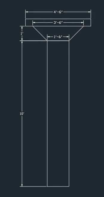
- Use the line and offset command to draw the standard front elevation of a drop column with the typical industry sizes.
- Now, switch back to the 3D plane by clicking on the home icon near the view cube.
- Create the rectangle of the XY dimensions as 4'-6"x4'-6".
- Use the extrude command and give the extrusion height as 6 inches.
- Then, create a line from the center of the 3d rectangle just created.
- Create a circle of the radius 9 inches anywhere in the model space near the object.
- Use the sweep option to give and first select the 9 inches radius circe and press enter.
- Then, select the vertical line and press enter to turn it into the circular column of 1'-6" diameter.
- Type in "HIDE" in the command panel to display the overall outlook of the drop column.
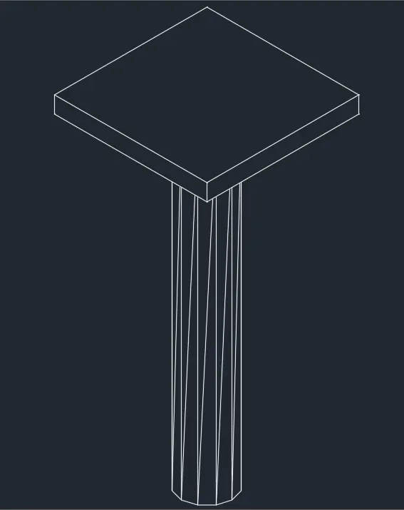
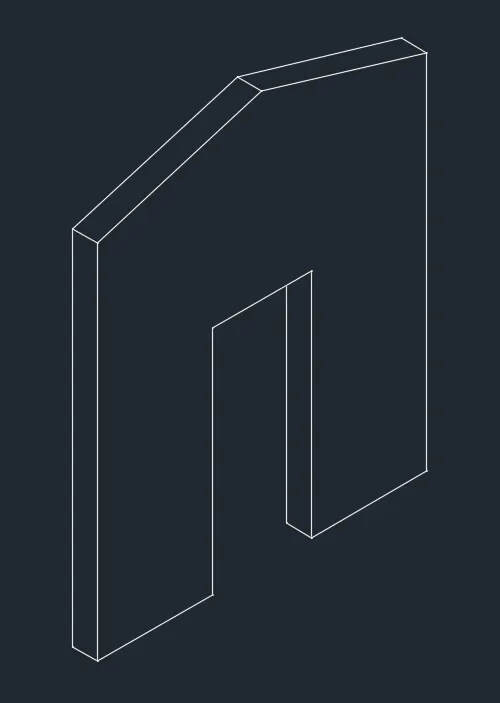
5. Creating the 3D Model of a Gable Wall with 9-inches Thickness to Showcase the Construction of Pitch Roof Starting from the top of the 3D Gable Wall Model.
STEPWISE PROCEDURE:
- Creating the Front Elevation of the Wall in 2D-plane.
- Switch the view from the 3d plane to the 2d top view by typing in "PLAN" in the command panel.
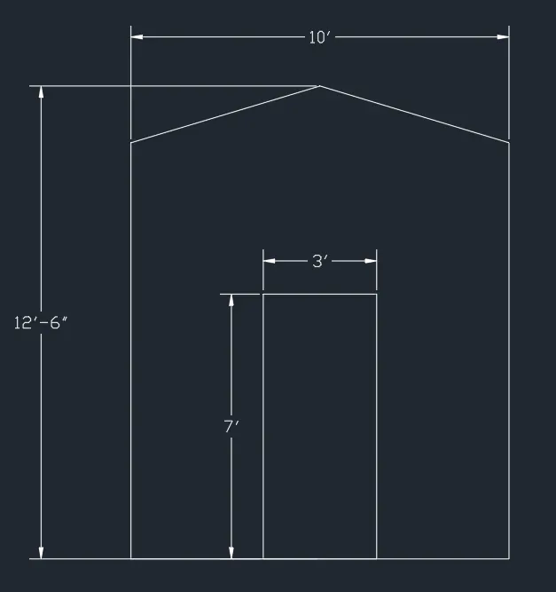
- Use the typical line, offset, rectangle, and other essential commands often used to create the 2d elevation.
- In the elevation, give the total height as 12' and take up the total length as 10'.
- Drawing the 3D model from the Front Elevation Created in the 2d Plane
- After drawing the front elevation in the 2d plane, shift back to the 3d modeling by clicking on the home icon in the view cube.
- Rotate the plan by using the rotate3d command in 3d modeling.
- Give the rotation angle of 90 degrees from the reference axis.
- After rotating, use the extrude command and extrude the wall for 9 inches in the positive Y direction.
- Do the same extrusion for the door.
- Then, subtract the door from the wall to showcase the 3' wide opening.
- Type in "HIDE" in the command panel to display the overall 3d outlook of the gable wall.