Creating various 3D Models like Furniture, Footing, Girder, Column drop with panel and Gable Wall in AutoCad
Q1
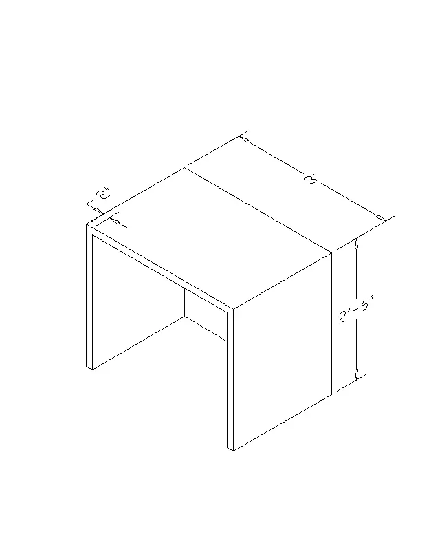
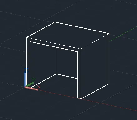
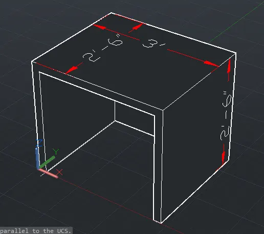
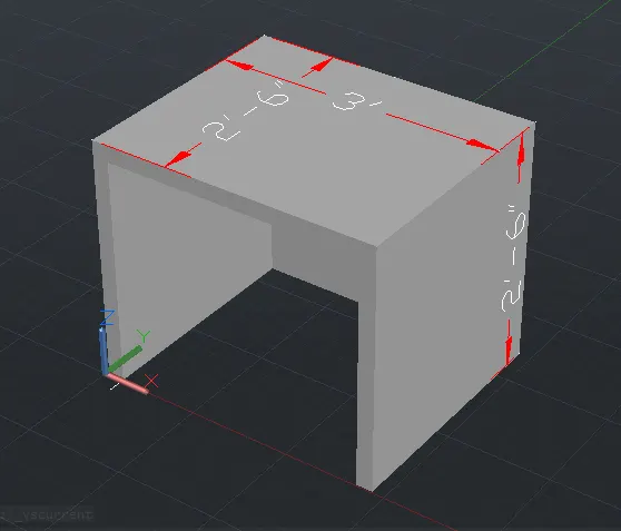
AIM : To create a 3D Furniture element as shown in the Figure. Assume dimensions which are missing.
PROCEDURE :
STEP 1 :
Open the New AutoCAD file, go to settings and change GUI to 3D modelling
STEP 2 :
Type unit or UN in the command box and press enter
Set type of unit as Engineering and precision as 0'0"
In Insertion scale set unit as Inches
STEP 3 :
Type dimension style manager or D in the command box and press enter
Modify primary units as Engineering and precision as 0'0"
STEP 4 :
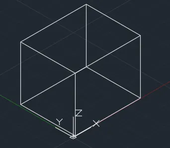
Type box in the command box and press enter
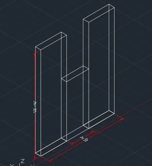
Select the first point and give the length of the box as 3', width of the box as 2'6" and height of the box as 2'6".
STEP 5 :
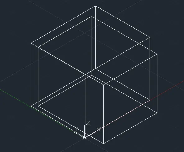
Type box in the command box and press enter
Select the first point and give the length of the box as 2'8", width of the box as 3' and height of the box as 2'4".
STEP 6 :
By using subtract option subtract the inner rectangle by selecting the outer rectangle.
STEP 7 :
Give the dimensions
RESULT :
The given figure is drawn using necessary tools in AutoCAD 3D Modelling
Q2
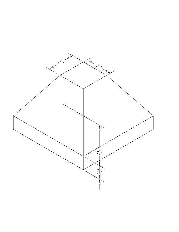
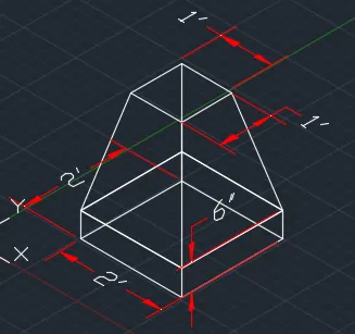
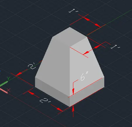
AIM : To create the 3d Model of an Isolated footing as shown in Figure.
PROCEDURE :
STEP 1 :
Open the New AutoCAD file, go to settings and change GUI to 3D modelling
STEP 2 :
Type unit or UN in the command box and press enter
Set type of unit as Engineering and precision as 0'0"
In Insertion scale set unit as Inches
STEP 3 :
Type dimension style manager or D in the command box and press enter
Modify primary units as Engineering and precision as 0'0"
STEP 4 :
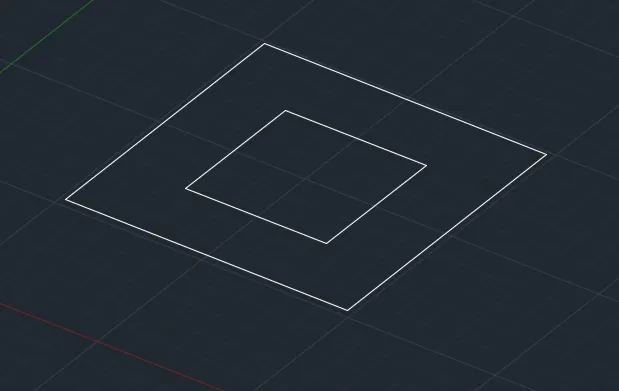
Draw a rectangle of 2', 2'. and offset of 0.5'
STEP 5 :
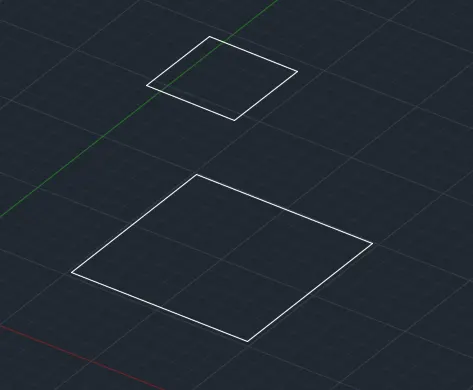
Move the inner rectangle in z axis at a height of 2'
STEP 6 :
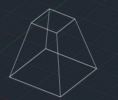
Select Loft from the tool bar and select the object to be lofted
STEP 7 :
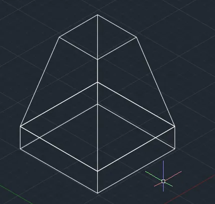
Draw a rectangle on the bottom of the bigger rectangle and region it.
Extrude the rectangle for 6".
STEP 8 :
Give the dimensions
RESULT :
The given figure is drawn using necessary tools in AutoCAD 3D Modelling
Q3
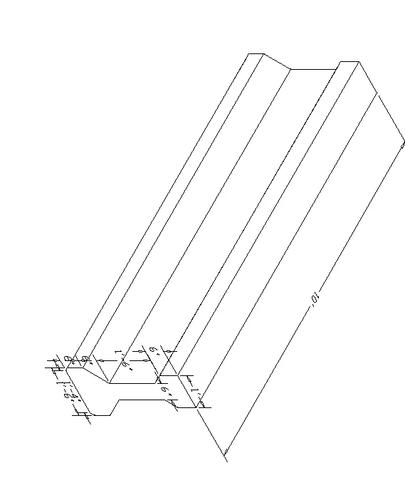
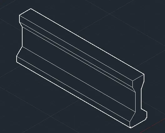
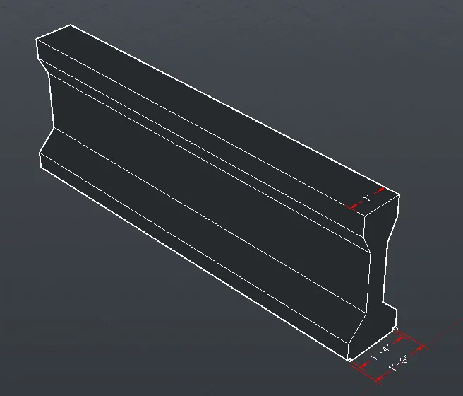
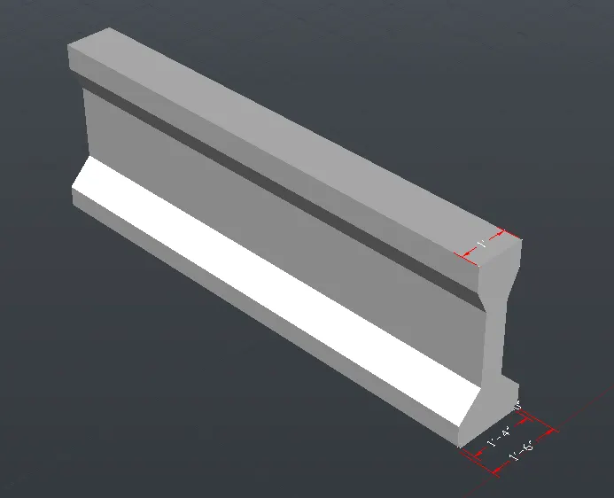
AIM : To create the 3D view of the AASTHO Type Girder.
PROCEDURE :
STEP 1 :
Open the New AutoCAD file, go to settings and change GUI to 3D modelling
STEP 2 :
Type unit or UN in the command box and press enter
Set type of unit as Engineering and precision as 0'0"
In Insertion scale set unit as Inches
STEP 3 :
Type dimension style manager or D in the command box and press enter
Modify primary units as Engineering and precision as 0'0"
STEP 4 :
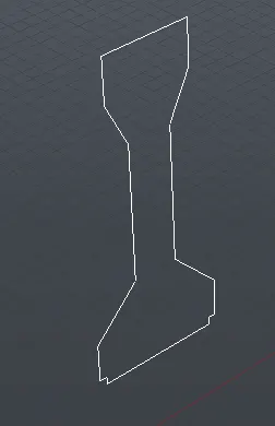
By using line command draw the frontview of the AASTHO Type Girder.
STEP 5 :
Region the object and extrude it for 10'
STEP 6 :
Give the dimensions
RESULT :
The given figure is drawn using necessary tools in AutoCAD 3D Modelling
Q4
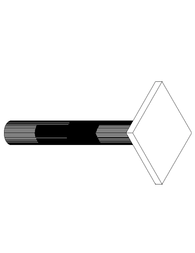
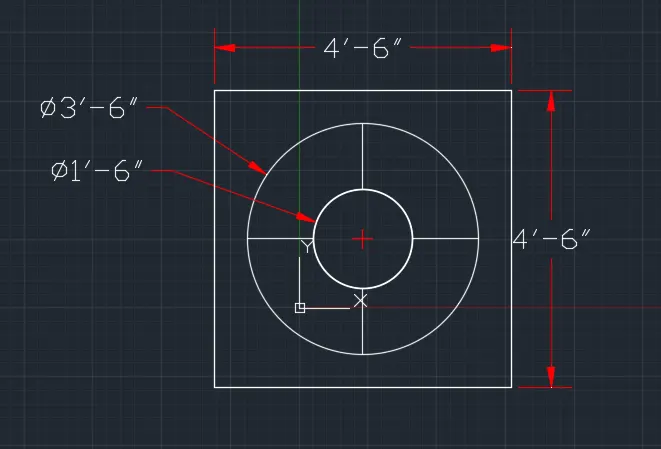
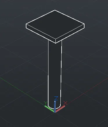
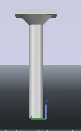
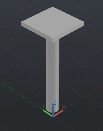
AIM : Create a 3d Model of a drop column with panel as shown in section and isometric view.
PROCEDURE :
STEP 1 :
Open the New AutoCAD file, go to settings and change GUI to 3D modelling
STEP 2 :
Type unit or UN in the command box and press enter
Set type of unit as Engineering and precision as 0'0"
In Insertion scale set unit as Inches
STEP 3 :
Type dimension style manager or D in the command box and press enter
Modify primary units as Engineering and precision as 0'0"
STEP 4 :
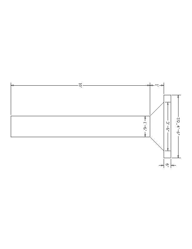
Draw a Circle of diameter 1'6" and region the object and extrude it for a height of 10'.
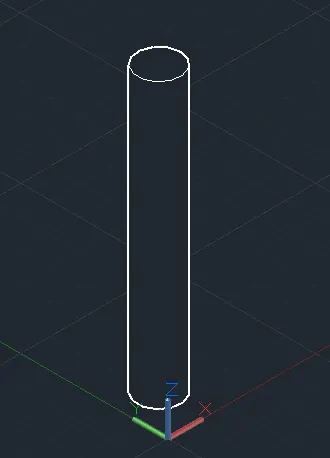
STEP 5 :
Draw a cone of diameter 1'6" and a top cone diameter as 3'6" and a height of 1' and press enter.
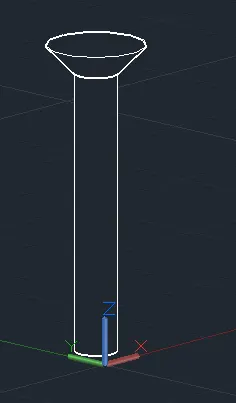
STEP 6 :
Draw a rectangle of size 4'6",4'6" and region the object and ectrude it for 6"
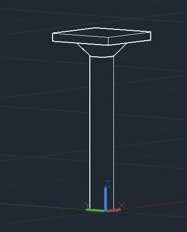
STEP 7 :
Give the dimensions
RESULT :
The given figure is drawn using necessary tools in AutoCAD 3D Modelling
Q5
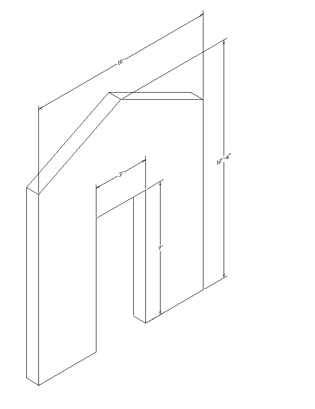
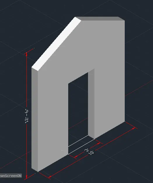
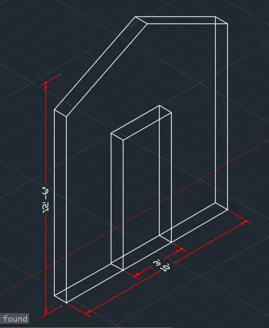
AIM : To create the 3d model of a wall as shown in Figure. Consider wall thickness as 9”.
PROCEDURE :
STEP 1 :
Open the New AutoCAD file, go to settings and change GUI to 3D modelling
STEP 2 :
Type unit or UN in the command box and press enter
Set type of unit as Engineering and precision as 0'0"
In Insertion scale set unit as Inches
STEP 3 :
Type dimension style manager or D in the command box and press enter
Modify primary units as Engineering and precision as 0'0"
STEP 4 :
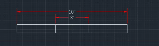
Draw a rectangle of size 10',9" and mark 3' door
STEP 5 :
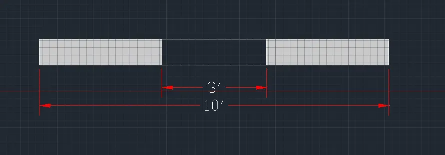
Using boundary command select the points tro create region on either side of the door
STEP 6 :
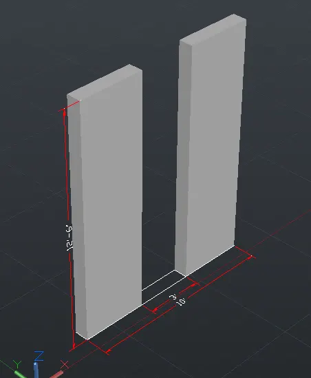
Extrude the region to a height of 12'6"
STEP 7 :
Draw a rectangle in the place of a door and move it to a height of 7'
STEP 8 :
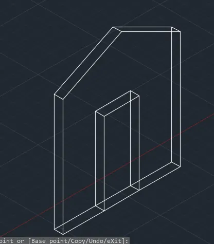
By using line command draw the roof of the elevation
use union command to make a single object
STEP 9 :
Give the dimensions
RESULT :
The given figure is drawn using necessary tools in AutoCAD 3D Modelling