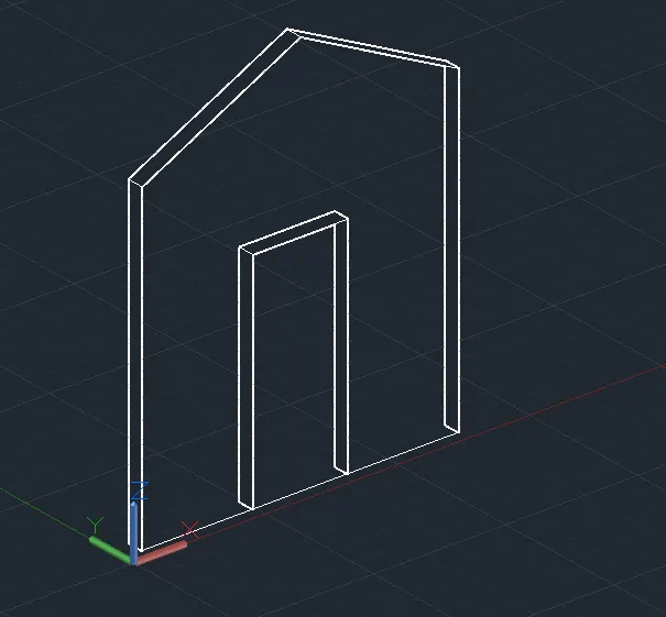
Creating various 3D Models like Furniture, Footing, Girder, Column drop with panel and Gable Wall in AutoCad
Q1
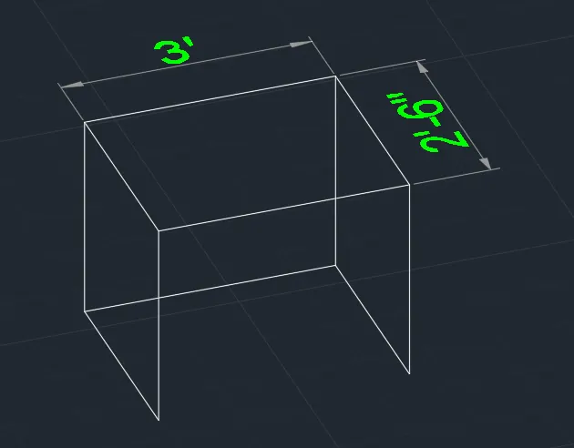
AIM:- To create a given object in the 3d
- firstly switch the drawing workspace from 2D to 3D basics
- set up the units of the drawing to the required units as (feet and inches)
- in the top view draw the rectangle as per the given dimensions
- then take a command 3DORBIT
- change the view of the drawing
- construct the other boundaries by taking the line command
- take a line command to build the side view
- specify the first point as the corner of the rectangle
- specify the next point as @0,0,- 2'6"
- specify the next point as @0,-2'6",0
- specify the next point as @0,0,2'6"
- similarly construct the side view on other side
- take a dim linear command
- specify the dimensions of the given figure
Q2
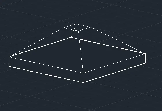
aim:-to create a given 3D Image
- take a rectangle command
- specify the first point
- specify the next point and create a rectangle
- create another rectangle of size 1'x 1'
- move the rectangle of size 1' x 1' to the distance of 2'
- take an extrude command
- select the rectangle at the base
- specify the extrude distance as 6"
- then take a 3DORBIT command
- change the view as per the requirement and join the corners of the rectangle on all sides
- change the type of drawing to hidden
- then the required image is created
Q3
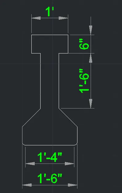
aim:- to recreate a given image as per the given dimensions
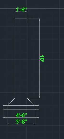
- take a line command
- create a front view of the given image
- take a 3DORBIT command
- rotate the image to the required view
- take a extrude command
- select the object to be extruded
- specify the extrude distance as 10'
- drag the object to extrude
- change the custom view to the hidden
- take a dim linear command
- specify the dimensions of the object
- then the required image is created
Q4
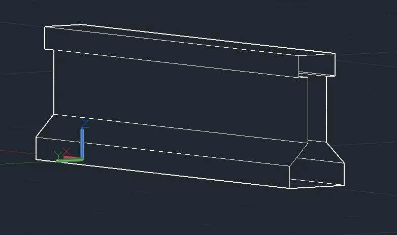
AIM:- To create a given image in the 3D format
- create a front view of the image
- to create a front view we will work on the xz plane
- take a line command
- specify the first point
- and draw the image as per the given dimensions
- then take a command 3DOBIT
- change the view as per the requirement
- take a command extrude
- select the rectangle to extrude
- and specify the distance
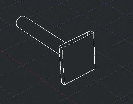
- now draw the line of 10' from the surface of the rectangle
- daw the circle of dia 1'6"
- take a sweep command
- select the circle object to sweep
- select the path of the sweep
- then click on ok
- then the required image is created
Q5
aim:- to create a given image as per the dimensions
- take a line command
- create a front view of the image as per the dimensions
- provide the opening door of size 3' x 7'
- then take a command 3DORBIT
- change the view of the drawing as per the requirement
- then take a command extrude
- select the object to be extruded
- specify the extrude distance
- then the change the view type of the drawing to shaded
- then subtract the solid object to provide an opening
- then the required image is formed