Creating various 3D Models like Furniture, Footing, Girder, Column drop with panel and Gable Wall in AutoCad
1)To create 3D furniture elements using Autocad.
AIM:-
PROCEDURE-
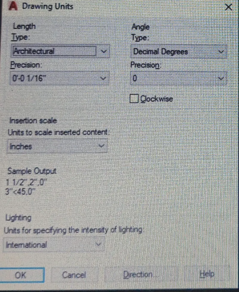
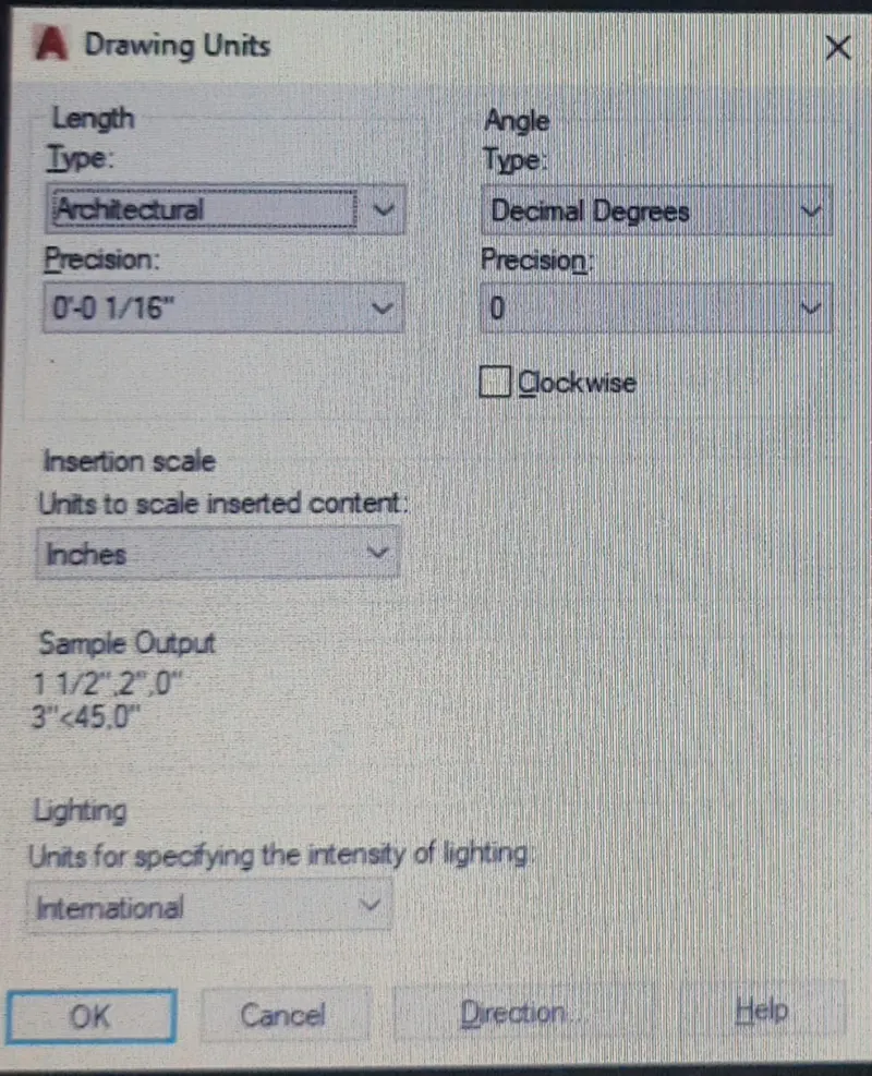
.Type 'UNITS' in the command prompt & press enter.
.In the unit tab select type as'ARCHITECHTURAL' intention scale as 'inches'.
.Click ok.
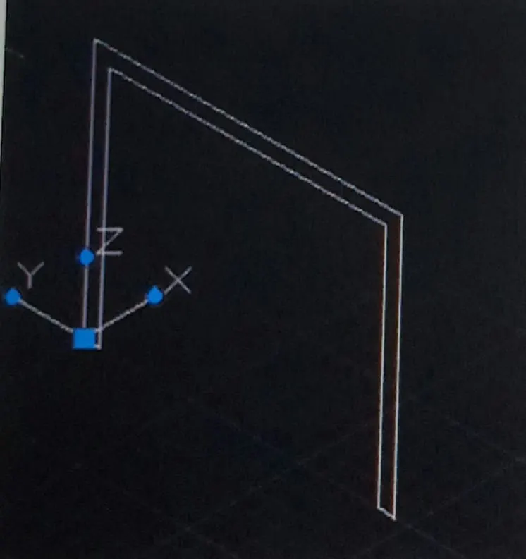
 .Type 'LINE' command prompt & press enter.
.Specify the starting point using the cursor.
.Enter the next point as @ (0,0,2'6")& press enter.
.Enter the next point as @ (0,0,3')& press enter.
.Enter the next point as @ (0,0,-2'6")& press enter.
.Enter the next point as @ (0,0,2'6")& press enter.
.Enter the next point as @ (0,2",0)& press enter.
.Enter the next point as @ (0,0,-2'6")& press enter.
.Enter the next point as @ (0,0,-2'6")& press enter.
.Click on close from the command prompt.
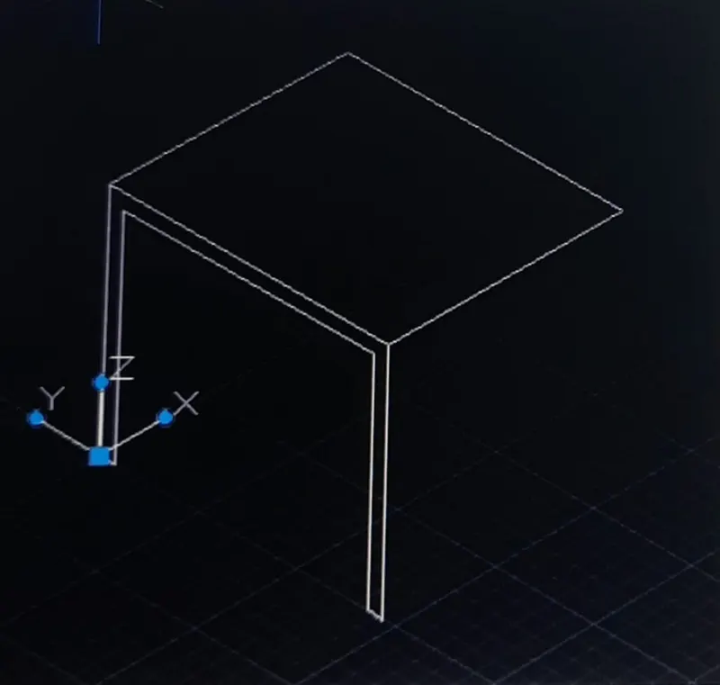
.Type 'LINE' command prompt & press enter.
.Specify the starting point using the cursor.
.Enter the next point as @ (2,0,0)& press enter.
.Enter the next point as @ (2,0,0)& press enter.
.Enter the next point as @ (0,-3,0)& press enter.
.Click on close from the command prompt.
.Type '3D FACE' in the command prompt & press enter.
.Specify the first ,second,third,fourth point.
.Press enter.
.Type hide in the command prompt & press enter.
.Type 3D orbit in the command prompt & press enter.
.Click & move the cursor to rotate the workspace.
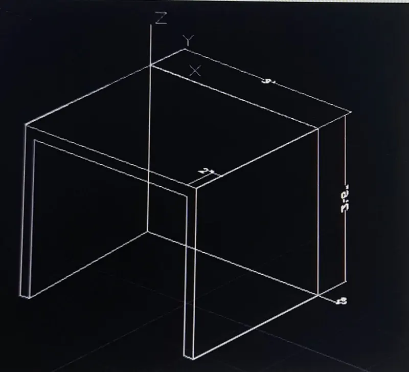
.In the ribbon tab under the co-ordinate select view from dropdown.
.Type 'DIMLENEAR' in the command prompt & press enter.
.Specify the starting & ending points to display the dimensions.
2)AIM:-To create a 3dmodel of isolated footing using the Autocad.
PROCEDURE:-
.Type 'UNITS' in the command prompt & press enter.
.In the unit tab select type as 'ARCHITECHTURAL' intention scale as 'inches'.
.Click ok.
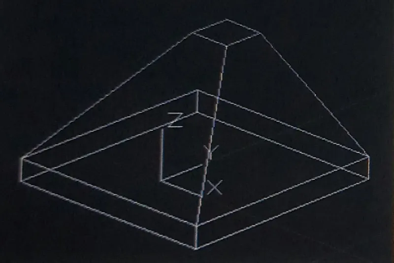
.Select the rectangle tool from the ribbon tab & press enter.
.Specify the starting point using the cursor.
.Click the dimensions from the command prompt & press enter.
.Enter the length as 1 & bredth as 1.
.Press Esc.
.Type offset in the command prompt & press enter.
.Enter the offset as distance as 2".
.Select the rectangle to offset.
Select the extrude from the ribbon tab & select the previously created object.
.Enter the height to extrude 6" & press enter.
.Select the rectangle that was created first type move in the command prompt & press enter.
.Select the object & enter the distance along which the object has to be moved.
.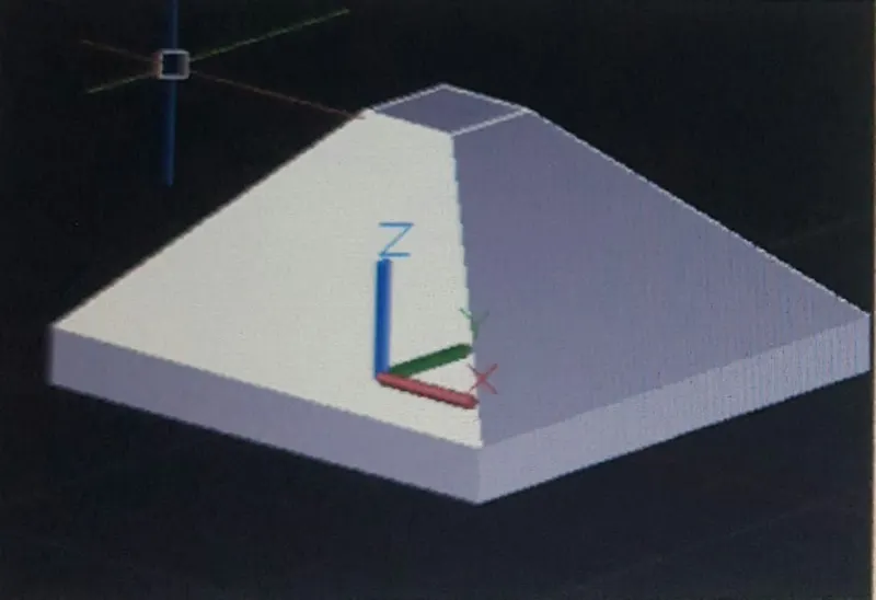
.In the layer properties, select the view as solid.
.Type '3D FACE' in the command prompt & press enter.
.Specify the first, second, third, fourth point.
.Press enter.
.Type hide in the command prompt & press enter.
.Type 3D orbit in the command prompt & press enter.
.Click & move the cursor to rotate the workspace.
.In the ribbon tab under the co ordinate select view from drop down.
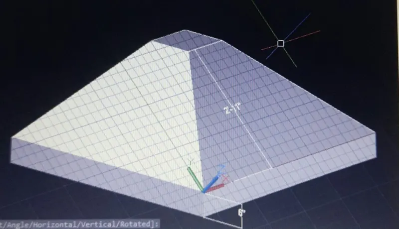
.Type 'DIMLENEAR' in the command prompt & press enter.
.Specify the starting & ending points to display the dimensions.
3)AIM:-To create 3d view of aastho type girder using Autocad
PROCEDURE:-
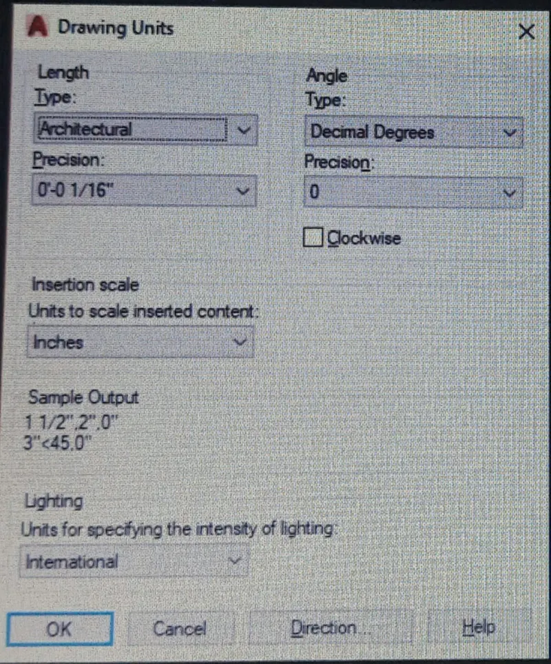
.Type 'UNITS' in the command prompt & press enter.
.In the unit tab select type as 'ARCHITECHTURAL' intention scale as 'inches'.
.Click ok.
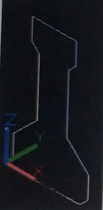
.Type 'LINE' command prompt & press enter.
.Specify the starting point using the cursor.
.Enter the next point as @ (0,2"0)& press enter.
.Enter the next point as @ (0,0,6")& press enter.
.Enter the next point as @ (4",0,6")& press enter.
.Enter the next point as @ (0,0,1'6")& press enter.
.Enter the next point as @ (-2,0,0)& press enter.
.Enter the next point as @ (0,0,'6")& press enter.
.Enter the next point as @ (6",0,0)& press enter.
.Press Esc.
.Select the created object & mirror in the command prompt.
.Select the suitable base point.
.Move the cursor to mirror the object.
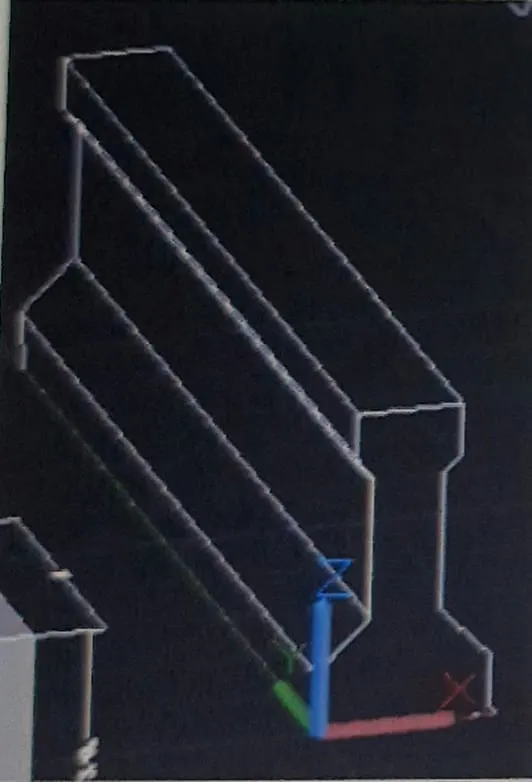
.Select the tool from the ribbon tab.
.Specify the starting point using the cursor.
.Enter the next point as @ (0,10',0) & press enter.
.Similarly, repeat the same method to create the line projecting backwards.
.Press Esc.
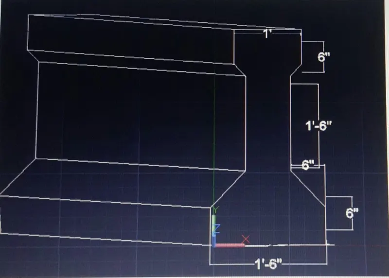
.Use line tool from ribbon tab to create the required object.
.Type '3D FACE' in the command prompt & press enter.
.Specify the first, second, third, fourth point.
.Press enter.
.Type hide in the command prompt & press enter.
.Type 3D orbit in the command prompt & press enter.
.Click & move the cursor to rotate the workspace.
.In the ribbon tab under the co ordinate select view from drop down.
.Type 'DIMLENEAR' in the command prompt & press enter.
.Specify the starting & ending points to display the dimensions.
4)AIM:-To create 3D model of drop column with panel using Autocad.
PROCEDURE:-
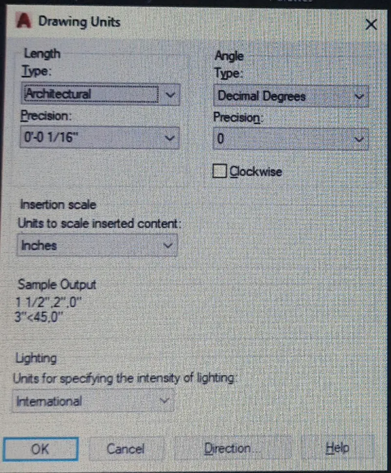
.Type 'UNITS' in the command prompt & press enter.
.In the unit tab select type as 'ARCHITECHTURAL' intention scale as 'inches'.
.Click ok.
.
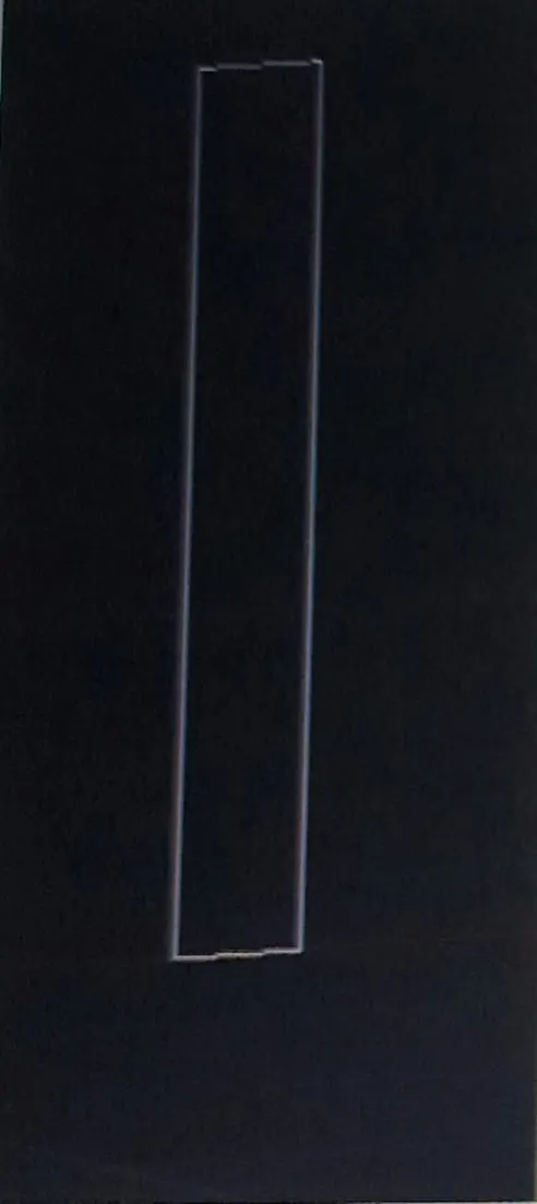
.Type 'LINE' command prompt & press enter.
.Specify the starting point using the cursor.
.Enter the next point as @ (0,0,10")& press enter.
.Enter the next point as @ (1'6",0,0)& press enter.
.Enter the next point as @ (0,0,-10")& press enter.
.Enter the next point as @ (1'6",0,0)& press enter.
.Press Esc.
.Type 'LINE' command prompt & press enter.
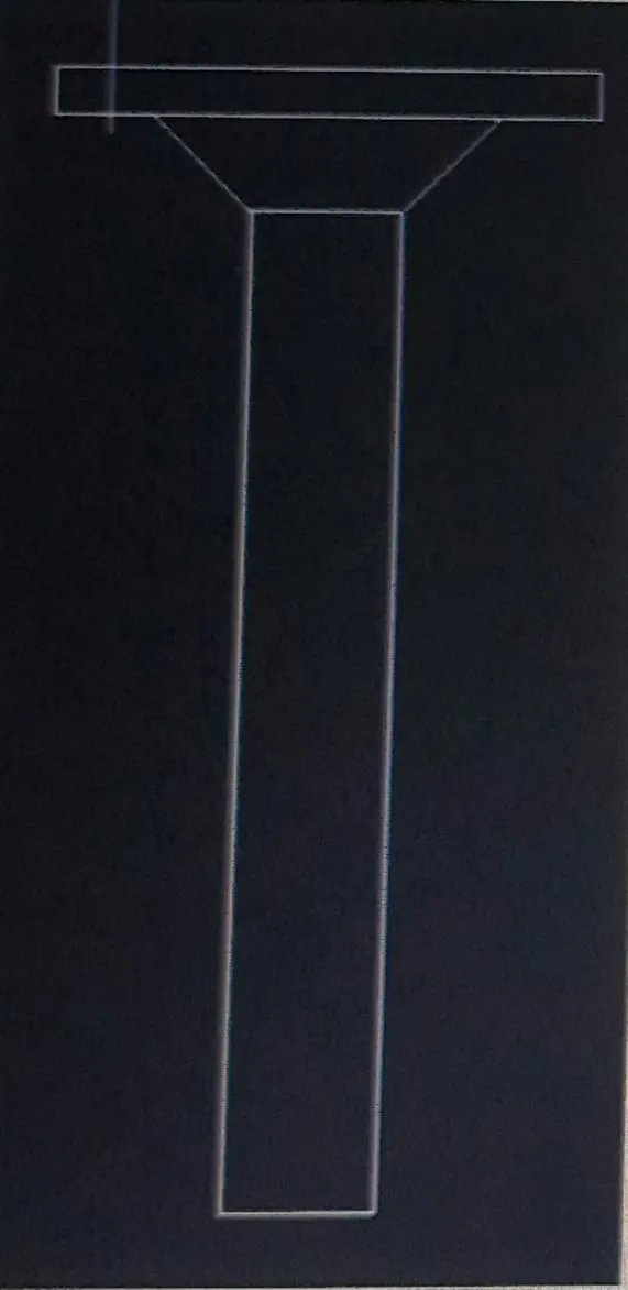
.Specify the starting point using the cursor.
.Enter the next point as @ (-1,0,1)& press enter.
.Enter the next point as @ (-1,0,0)& press enter.
.Enter the next point as @ (0,6,0)& press enter.
.Enter the next point as @ (4'6",0,0)& press enter.
.Enter the next point as @ (0,-6,0)& press enter.
.Enter the next point as @ (-1,0,0)& press enter.
.Enter the next point as @ (-1,0,-1)& press enter.
.Press Esc.
.In the ribbon tab under the co ordinate select view from drop down.
.Type 'DIMLENEAR' in the command prompt & press enter.
.Specify the starting & ending points to display the dimensions.
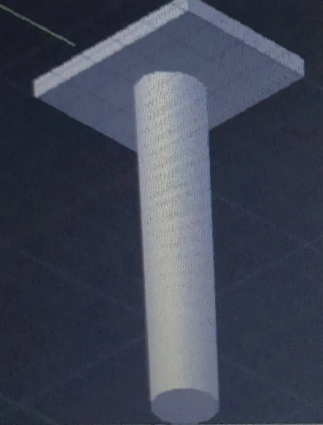
5)AIM:- To create 3d model using Autocad.
PROCEDURE:-
.Type 'UNITS' in the command prompt & press enter.
.In the unit tab select type as 'ARCHITECHTURAL' intention scale as 'inches'.
.Click ok.
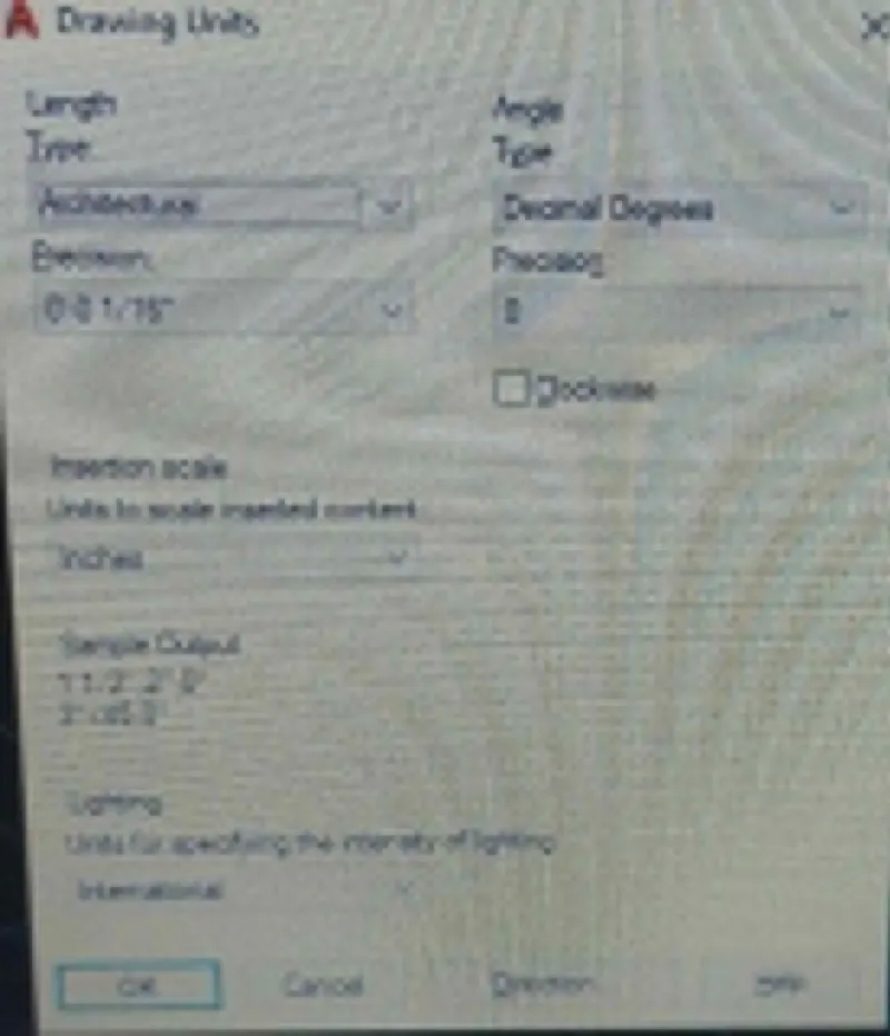
.Select the top view from the cube.
.Select the rectangle tool from the ribbon tab.
.Specify the starting point press enter.
.Select the dimension from the ribbon tab.
.Enter the length & breadth.
.Press Esc.
.Select the circle tool from the ribbon tab
.Specify the center & drag the cursor to create the circle.
.Press Esc.
.Select Extrude from the ribbon tab & select the circle tab.
.Enter the extrude height as -10 & press enter.
.Again select rectangle object & click on extrude.
.Again the extrude height is 6.
.Type hide in the command prompt & press enter.
.Type 3D orbit in the command prompt & press enter.
.Click & move the cursor to rotate the workspace.
.In the ribbon tab under the co ordinate select view from drop down.
.Type 'DIMLENEAR' in the command prompt & press enter.
.Specify the starting & ending points to display the dimensions.
6)AIM:-To create 3d model of gable wall using AUTOCAD.
PROCEDURE-
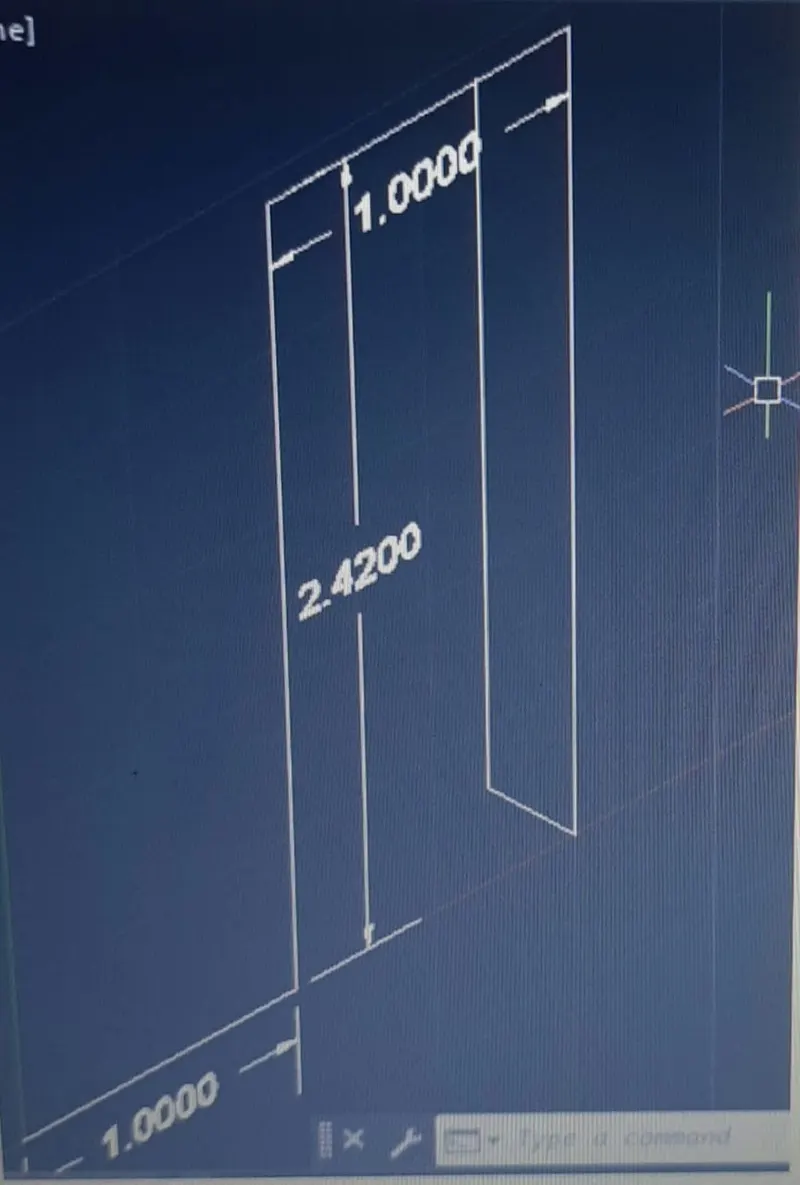
STEP1:-
.In the workspace click on view control icon in the left top corner.
.Select 'SW isometric' from the view control.
.Select line tool from the ribbon tab.
.Click on any point & enter the length as 1 keeping the cursor in Y direction.
.Enter the length as 2.42 & click keeping the cursor in Y direction.
.Enter the length as 1 & click keeping the cursor in Y direction.
.Enter the length as 2.42 & click keeping the cursor in negative Y direction.
.Enter the length as 0.3 & click keeping the cursor in negative Y direction.
.Press Esc.
STEP 2:-
.Select the line tool from the ribbon tab.
.Click on any point & Enter the length as 1 & click keeping the cursor in X direction.
.Enter the length as 3 & click keeping the cursor in Y direction.
.Draw a line of 0.83 unit length from the mid point of door panel connecting previous line.
.From the origin draw a line using line tool.
.Enter the length as 3 & click keeping the cursor in Y direction.
.Draw & join the line to the mid point using line command.
.Press Esc.
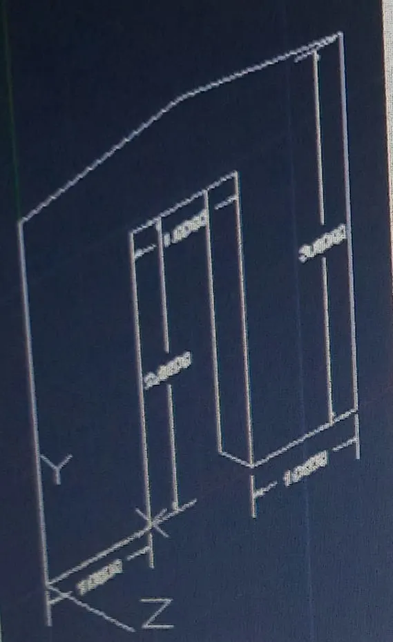
STEP3:-
.Select the line tool from the ribbon tab.
.From the origin draw a line using line tool.
.Click on point & enter the length as 0.3 keeping the cursor in negative Z direction.
.Enter the length as 3 & click keeping the cursor in Y direction.
.Enter the length as 1.5 & click keeping the cursor in X direction.
.Enter the length as 1.5 & click keeping the cursor in X direction.
.Press Esc.
.Draw a line of length of 0.3 unit joining midpoint of corner points using line command.
.Press Esc.
