Creating various 3D Models like Furniture, Footing, Girder, Column drop with panel and Gable Wall in AutoCad
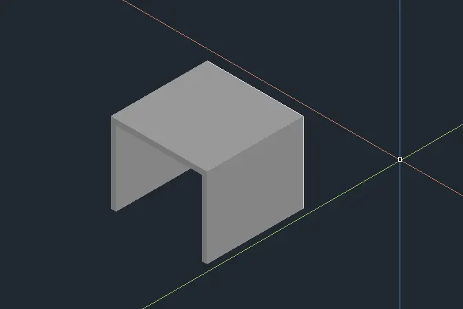
1. Create a 3D Furniture element as shown in the Figure. Assume dimensions which are missing.
Aim:
To create a 3D Furniture Element using the Various commands in Auto CAD.
Introduction Of 3D View:
- A Software which you can realize the Relity of an object in 3D drawing
- The process of creating a mathematical representation of any surface of an object in three dimensions by using special software.
- A 3D model can even be represented as a two Dimenesional image by using the 3D rendering process.
- It enables the professional creation and edition of 2D geometry and 3D models with solids, Surface and object.
Commands Used:
- Line.
- Offset.
- Extrude.
- Erase.
- Trim.
Procedure:
- To create a new sheet from application of Auto CAD.
- Go to the Setting and to change the view of the page from Drafting to 3D Modeling
- Type Unit to set the measurement in engineering (Feet and Inches).
- Type limits to set the maximum Dimension limits on the perticular page.
- First we take the top view of the page.
- Type "REC" to create a rectangle with a deimension of 2'6'' by 3'0''
- And we take to a 3D custom view.
- Type "3D ORBIT" to view a 3D orbit viewport in the current view.
- Then we take a all dimension to create it from the orgin point is (0,0,0)
- Next point we take to x direction of (@2'6'' , 0, 0).
- Type Extrude to create a surface of solid of a 2D Surface.
- Then we have to change the view of 2D Wire, shaded,conceptual ,Etc.
- Type "3D FACE" for allows to generate 3D faces by identifying.
- To save the diagram to perticular file.
RESULTS:
The diagram of 3D furniture elements is drawn as per dimension using the Software of Auto CAD.
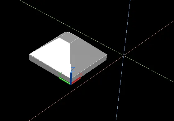
2. Create the 3d Model of an Isolated footing as shown in Figure.
Aim:
To create a 3D Model of an isolated Footing using the Various commands in Auto CAD.
Commands Used:
- Line.
- rectangle.
- Offset.
- Extrude.
- Erase.
- Trim.
- Move.
- loft
Procedure:
- To create a new sheet from application of Auto CAD.
- Go to the Setting and to change the view of the page from Drafting to 3D Modeling
- Type Unit to set the measurement in engineering (Feet and Inches).
- Type limits to set the maximum Dimension limits on the perticular page.
- First we take the top view of the page.
- Type "REC" to create a rectangle with a deimension of 2'6'' by 3'0''
- And we take to a 3D custom view.
- The Footing dimension is 4'0'' by 4'0''.
- The depth of Footing is 6'' and reduced to the depth of 2'' and width 1'0''
- Copy this commands is used to selected objects from a given Square to detination, Learning a copy at the orginally selected location
- Move the Object to the destination place from the source place.
- And then to join the all lines.
- Type "3D ORBIT" to view a 3D orbit viewport in the current view.
- Type "3D FACE" for allows to generate 3D faces by identifying.
- To save the diagram to perticular file.
RESULTS:
The diagram of 3D Model of an Isolated Footing is drawn as per dimension using the Software of Auto CAD.
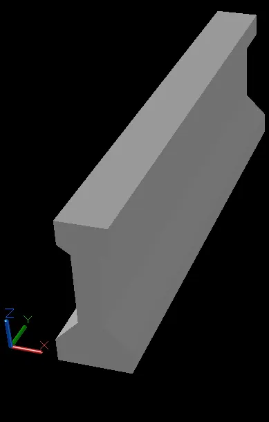
3. Create the 3D view of the AASTHO Type Girder.
Aim:
To create a 3D Model of an AASTHO Type Girder using the Various commands in Auto CAD.
Commands Used:
- Line.
- Offset.
- Extrude.
- Erase.
- Trim.
Procedure:
- To create a new sheet from application of Auto CAD.
- Go to the Setting and to change the view of the page from Drafting to 3D Modeling
- Type Unit to set the measurement in engineering (Feet and Inches).
- Type limits to set the maximum Dimension limits on the perticular page.
- First we take the top view of the page.
- Type "LINE" to create a line to draw the I section AASTHO Girder.
- The origin point is 0,0,0
- The next point is (@1'6'',0,0)
- The next point (@0,0,6'')
- The next point is (@6''<o<135) and to follow the all given dimension to draw the section.
- Type "3D ORBIT" to view a 3D orbit viewport in the current view port.
- Type "3D FACE" for allows to generate 3D faces by identifying.
- The "REGION" to converts onject that encloses an area into a 2D region Objects.
- Type "EXTRUDE" to create a surface or solid of a 2D surface or a 3D Curve.
- The extrude length of the section Girder is 10 Feet.
- Then, we have to change the view of 2D wire, shaded, conceptual etc.
- To save the diagram to perticular file.
RESULTS:
The diagram of 3D Type of AASTHO Girder is drawn as per dimension using the Software of Auto CAD.
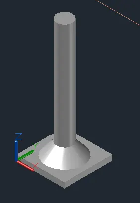
4. Create a 3d Model of a drop column with panel as shown in section and isometric view.
Aim:
To create a 3D Model of a drop column with panel using the Various commands in Auto CAD.
Commands Used:
- Line.
- Offset.
- Extrude.
- Erase.
- Trim.
- Move.
- Rectangle.
- Circle.
- loft.
Procedure:
- To create a new sheet from application of Auto CAD.
- Go to the Setting and to change the view of the page from Drafting to 3D Modeling
- Type Unit to set the measurement in engineering (Feet and Inches).
- Type limits to set the maximum Dimension limits on the perticular page.
- First we take the top view of the page.
- Type "REC" to create a rectangle with a deimension of 2'6'' by 3'0''
- And we take to a 3D custom view.
- To choose the Top view of page.
- the rectangular size is 4'6''
- Type "C" to create a circle options.
- The column head thickness is 6 inch.
- The height of the column is 10 feet.
- Copy this commands is used to selected objects from a given Square to detination, Learning a copy at the orginally selected location
- Move the Object to the destination place from the source place.
- After completed the copy of rectangle to make the box like structure of column head.
- After we take to draw a circle of diameter of 1'6''.
- Type "EXTRUDE" to create a surface or solid of a 2D surface or a 3D curve.
- The extruded length of the circular column with a negative direction of Z is 10 feet.
- Type "3D ORBIT" to view a 3D orbit viewport in the current view port.
- Type "3D FACE" for allows to generate 3D faces by identifying.
- Type " REGION" to converts objects that encloses an area into a 2D region Objects.
RESULTS:
The diagram of 3D Type of a column with drop panel is drawn as per dimension using the Software of Auto CAD.
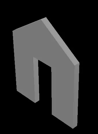
5. Create the 3d model of a wall as shown in Figure. Consider wall thickness as 9”.
Aim:
To create a 3D Model of a wall using the Various commands in Auto CAD.
Commands Used:
- Line.
- Offset.
- Extrude.
- Erase.
- Trim.
Procedure:
- To create a new sheet from application of Auto CAD.
- Go to the Setting and to change the view of the page from Drafting to 3D Modeling
- Type Unit to set the measurement in engineering (Feet and Inches).
- Type limits to set the maximum Dimension limits on the perticular page.
- First we take the top view of the page.
- Before we start the 3D work to create a plan of wall at 2D.
- To make wall thickness of 250mm.
- To fix the door and wall opening from wherever we need.
- Type" REGION" to convert objects that encloses an area into a 2D region curve.
- After creating perfect plan to do next work of 3D Solid works.
- Type "EXTRUDE" to create a surface or solid of a 2D surface or a 3D curve.
- The extuded of wall height is 10 feet from the base.
- And then to draw the rectangle of wherever having the doors and windows.
- This comes after to follow the extruded of door opening height of 7 feet.
- Type "3D ORBIT" to view a 3D orbit viewport in the current view port.
- Type "3D FACE" for allows to generate 3D faces by identifying.
- Type "REGION" to converts object that encloses.
- Type " SUBSTRACT" to remove the open required places of doors and windows.
- To save the diagram to perticular file.
RESULTS:
The diagram of 3D Type of a wall is drawn as per dimension using the Software of Auto CAD.
Overall RESULTS: