Creating various 3D Models like Furniture, Footing, Girder, Column drop with panel and Gable Wall in AutoCad
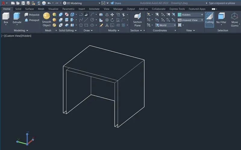
1. Create a 3D Furniture element as shown in the Figure. Assume dimensions that are missing.
AIM:
To create a 3D Furniture element as shown in the Figure.
REQUIRED TOOLS:
LINE
3D FACE
3D ORBIT
VIEW
REGION
PROCEDURE:
LINE:
Drawn a line with by using a Relative coordinate system,
start the line by selecting the point on the screen, then draw a line in Z-axis @0,0,2'-6',
draw a line in X-axis @2'-6",0,0
draw a line in Y-axis @0,3',0
draw a line in Z-axis @0,0,-2'-6"
draw a line in X-axis @-2'-6",0,0
draw a line in Z-axis @0,0,2'-6"
draw a line in Y-axis @0,-3',0
Creating the Thickness of the Table:
Select the starting point at the bottom corner
draw a line in Y-axis @0,-2",0
draw a line in Z-axis @0,0,2'-4"
draw a line in Y-axis @0,-2'-8",0
draw a line in Z-axis @0,0,-2'-4"
draw a line in Y-axis @0,-2",0
Creating the Side Faces:
REGION
Joining all the lines and making as a single closed entity.
COMMAND: REG>
Select the object>
VIEW
Changing the view from 2Dwireframe to SHADED view
3DFACE:
Creating the 3D face for the 2D wireframed object
COMMAND: 3F>
Select all the corners of the face> the shaded face will be appear
Create all the faces by using the 3DFace command.
3DORBIT
It helps to the orbiting the object in different kinds of directions.
COMMAND: 3DO>
RESULT:
Creating the 3D Furniture element by using the Relative Co-ordinate system and various tools and commands.
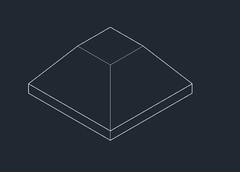
2. Create the 3d Model of an Isolated footing as shown in Figure.
AIM:
To create the 3d Model of an Isolated footing as shown in Figure.
REQUIRED TOOLS:
BOX
PYRAMID
VIEW
3DORBIT
PROCEDURE:
Creating the Base of the footing:
BOX:
COMMAND: BOX>
Create the base of the footing by using the Box command length and width taken as 5' and thickness 6".
PYRAMID:
Creating the Isolated Footing by using the PYRAMID command.
COMMAND: PYR>
Select the Edge option
Select the Edges of the BOX and select the Top radius option
The Top radius of the PYRAMID is 1'
The height of the Pyramid is 2'
VIEW:
Choose the HIDDEN View
It hides all inside lines.
RESULT:
Sketch out the Isolated Footing by using the Box and Pyramid Tools and other commands
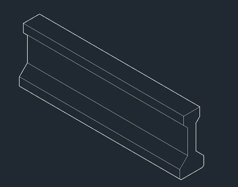
3. Create the 3D view of the AASTHO Type Girder.
AIM:
To create the 3D view of the AASTHO Type Girder.
REQUIRED TOOLS:
LINE
REGION
EXTRUDE
3DORBIT
VIEW
PROCEDURE:
Creating the 3D view of the Girder with a Relative coordinate system by using the Line tool.
Start the first point of line on the window
Drawn a line in X-axis @1'-4",0,0
Drawn a line in X-Z plane @1",0,1"
Drawn a line in Z-axis @0,0,6"
Drawn a line in X-Z plane @-6",0,6"
Drawn a line in Z-axis @0,0,1'-6"
Drawn a line in X-Z plane @3",0,3"
Drawn a line in Z-axis @0,0,6"
Drawn a line in Z-axis @-1',0,0
Drawn a line in Z-axis @0,0,-6"
Drawn a line in X-Z plane @3",0,-3"
Drawn a line in Z-axis @0,0,-1'-6"
Drawn a line in X-Z plane @-6",0,-6"
Drawn a line in Z-axis @0,0,-6"
Drawn a line in X-Z plane @1",0,-1"
REGION:
Command: REG>
Select the object >
It converts the object into a closed single entity.
EXTRUDE:
Extruding the object by using Extrude command
Invoking the tool:
COMMAND: EXT>
select the object to extrude and stretch the object in a parallel direction.
VIEW:
Choose the HIDDEN View
It hides all inside lines.
RESULT:
Created the 3D view of the AASTHO type Girder by using the Relative coordinate system and other Commands.
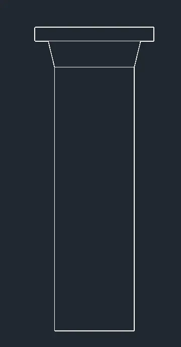
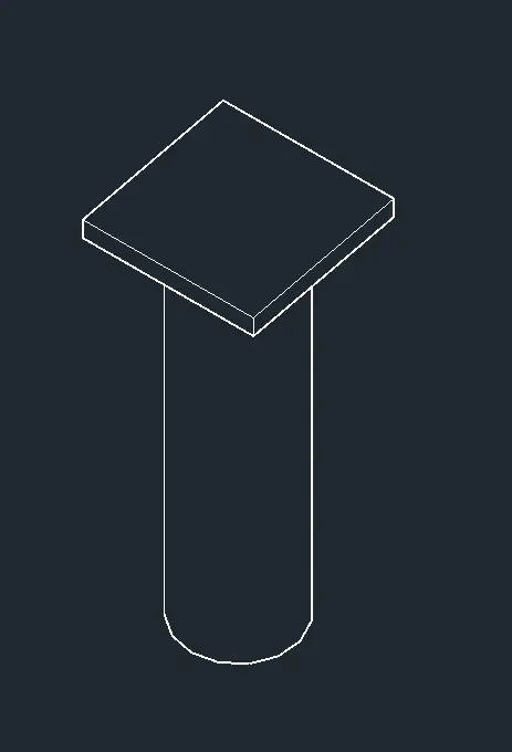
4. Create a 3d Model of a drop column with a panel as shown in section and isometric view.
AIM:
To create a 3d Model of a drop column with a panel
REQUIRED TOOLS:
RECTANGLE
CIRCLE
EXTRUDE
CONE
PRESSPULL
VIEW
3DORBIT
PROCEDURE:
Creating the square with dimensions of 4'-6" X 4'-6" in 2D wireframe.
Invoking tool:
COMMAND: REC>
Select the first corner point and give the dimension in X-axis 4'-6" and in Y-axis 4'-6" >
CIRCLE:
COMMAND: C>
Create a circle in the center of the square box with a diameter of 3'-6"
REGION:
The region to the object for having a single entity
COMMAND: REG>
Select the object to the region.
EXTRUDE:
Invoking tool:
COMMAND: EXT>
select the object to extrude
Extrude the square object to 6" >
CONE:
Creating the trunked shape object
INVOKING TOOL:
COMMAND: CONE>
select the center point of the circle on the square box
specify the diameter 3'-6" >
select the TOP RADIUS option>
Specify the diameter of the other end is 1'-6" >
specify the height of the Trunked object is 1' >
PRESSPULL:
For creating the column extruding the object from the trunked-shaped object.
Invoking the tool:
COMMAND: PRESSPUL>
Select the object and extrude 10' height.
VIEW:
Choose the HIDDEN View
It hides all inside lines.
RESULT:
Creating the 3D model of a drop column by using various commands and tools.
SECTIONAL VIEW
ISOMETRIC VIEW
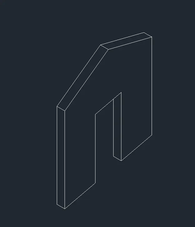
5. Create the 3d model of a wall as shown in Figure. Consider wall thickness as 9”.
AIM:
To create the 3d model of a wall as shown in Figure.
REQUIRED TOOLS:
LINE
3DORBIT
VIEW
PROCEDURE:
Creating the 3D model of a wall with a Relative coordinate system by using the Line tool.
Start the first point of line on the window
Drawn a line in Y-axis @0,9",0
Drawn a line in Z-axis @0,0,10'
Drawn a line in X-Z plane @5',0,2'-6"
Drawn a line in X-Z plane @5',0,-2'-6"
Drawn a line in Y-axis @0,-9",0
Drawn a line in Z-axis @0,0,-10'
Drawn a line in X-axis @-3'-6",0,0
Drawn a line in Z-axis @0,0,7'
Drawn a line in X-axis @-3',0,0
Drawn a line in Z-axis @0,0,-7'
Drawn a line in X-axis @-3'-6",0,0
Drawn a line in Z-axis @0,0,10,
Drawn a line in X-Z plane @5',0,2'-6"
Drawn a line in X-Z plane @5',0,-2'-6"
Creating corners of the walls by copying
REGION:
The region to the object for having a single entity
COMMAND: REG>
Select the object to the region.
VIEW:
Choose the HIDDEN View
It hides all inside lines.
RESULT:
Creating the 3D model of a wall by using the Relative coordinate system