Creating various 3D Models like Furniture, Footing, Girder, Column drop with panel and Gable Wall in AutoCad
WEEK 12 CHALLENGE REPORT
- Aim is to create the 3D furniture element as shown in the figure using 3D Modeling Workspace. I am going to use UCS Icon, View Cube and Navigation Bar to work easily in different sides of the drawing.
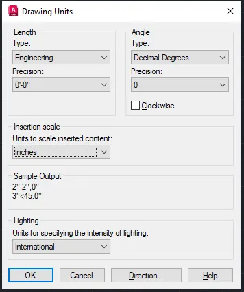
- First step is to open a new page and set the Drawing Units as shown.
- Next I set the max limit of the screen using Command: Limmax 20’,20’
Command: Zoom > All
- Now I Switch the working space
Workspace Switching> From Drafting and Annotation to 3D Modeling
- Is time to start with the drawing of the furniture element.
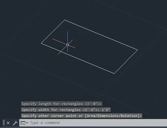
First thing I do is draw a rectangular using command: Rec with length 3’ and width 1’6”.
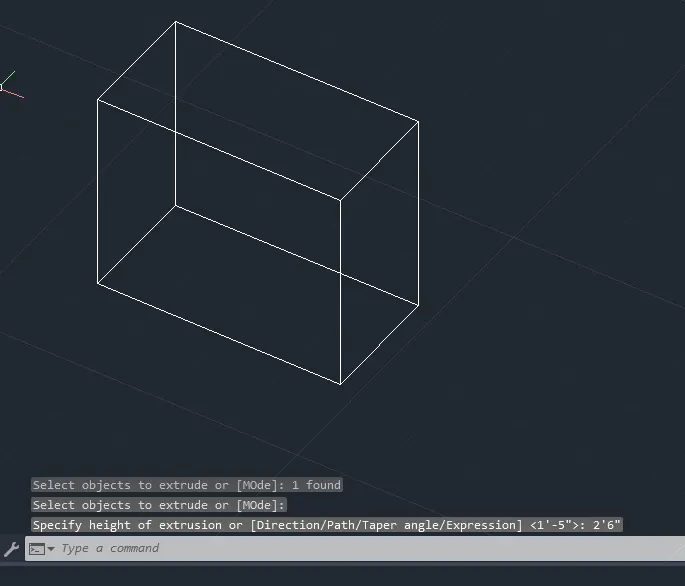
- Using command: Extrude I extrude the rectangular with hight of extrusion 2’6”.
- I change the UCS position using command: UCS as shown, and then draw a rectangular same as the face where we placed the UCS , and Offset these rectangular 2”. Then I delete the first rectangular.
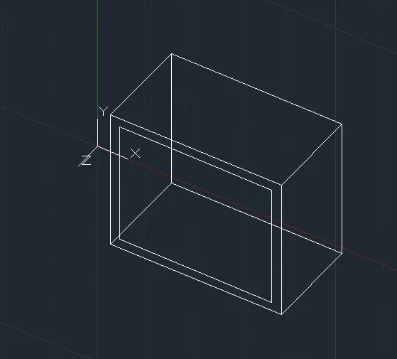
- I explode the offseted rectangular, extend the right and left side as shown, and move the bottom side down.
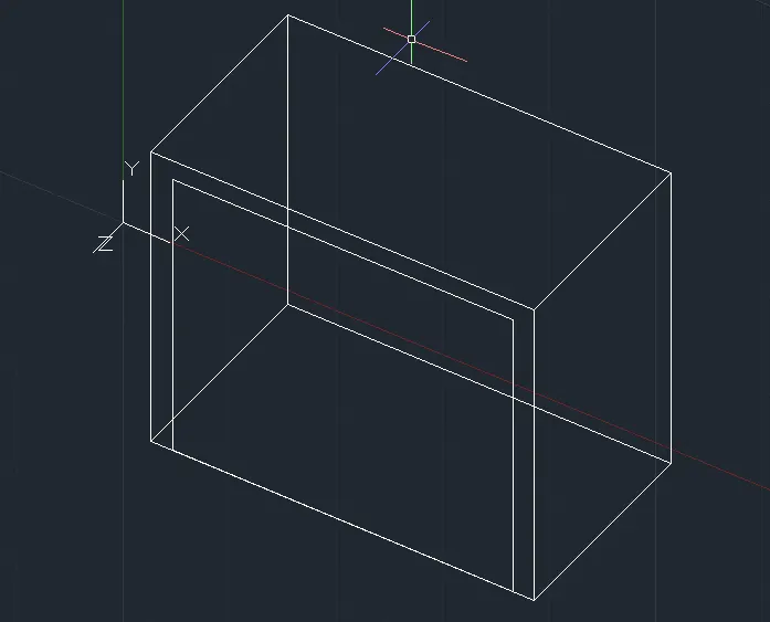
- Using command : Boundary I Region the rectangular created resently.
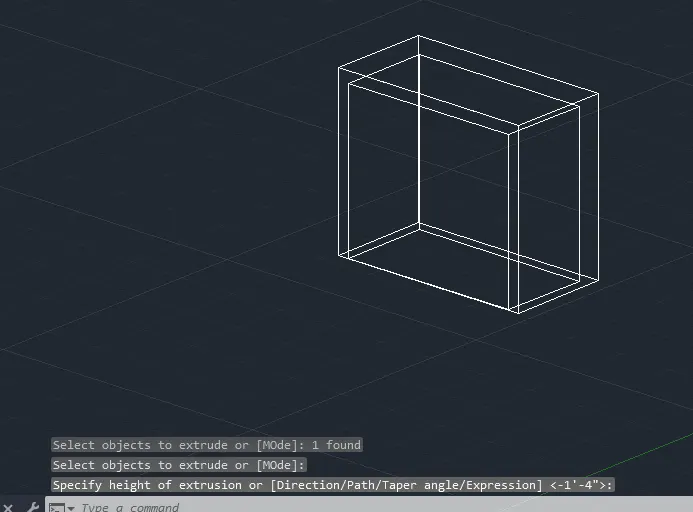
- Then using command: Extrude I extrude the rectangular with high of extrusion 1,4”
- Using command: Subtract I subtract the iner box from the initial box.
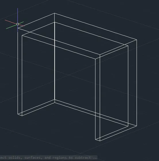
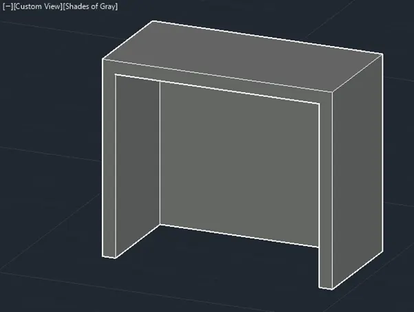
- This is the 3D furniture element in a shade of grey.
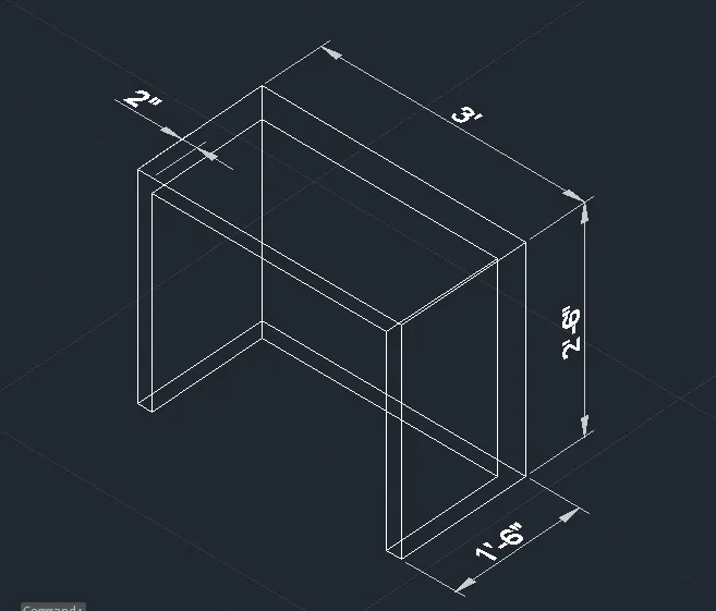
- This is the 3D furniture element with dimmensions.
To dimension it first using command: D for dimension style manager , I Create a dimension style with text high 2.5”.
Then I change the UCS position using command: UCS, as required to dimension the element using command: DIMLIN.
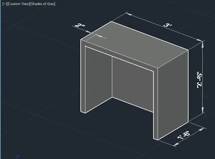
- This is the final result of the 3D Furniture Element in a shade of Grey.
2.Aim is to create the 3D model of an Isolated footing as shown in the figure using 3D Modeling Workspace. We are going to use 3D commands: Extrude and Pyramid in order to finish the model. I am going to use UCS Icon, View Cube and Navigation Bar to work easily in different sides of the drawing.
- First we use command:Plan to show in the screen the XY plan.
Then in this plan I draw a rectangular 2’x2’.
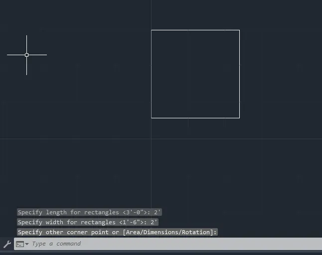
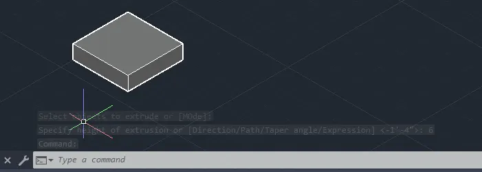
- Then using command Extrude, I extrude it with heigh 6”.
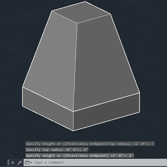
- Using command: Pyramid with top radius 6” and high 2’.
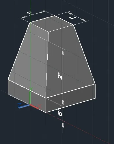
- This is the final 3D model of the Isolated footing with dimmensions.
To dimension it first using command: D for dimension style manager , I Create a dimension style with text high 3”.
Then I change the UCS position using command: UCS, as required to dimension the element using command: DIMLIN.
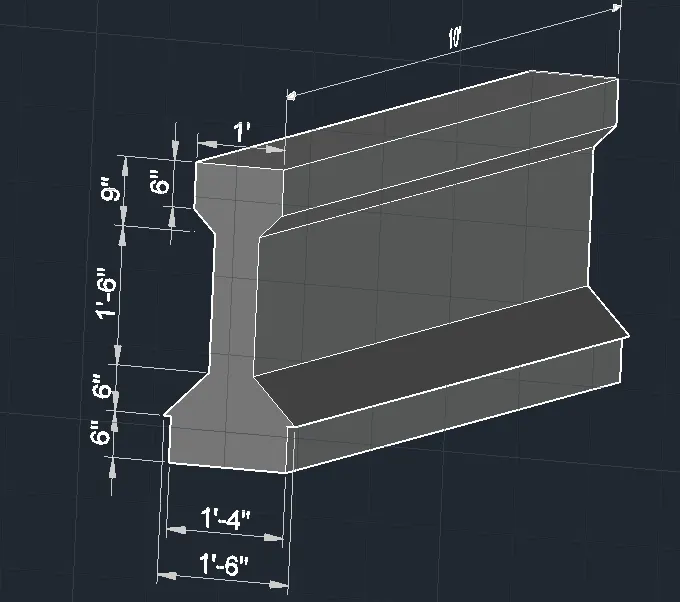
3.Aim is to create the 3D view of the AASTHO Type Girder using 3D Model Workspace. I am going to use commands: Line, Mirror, Region, Extrude.. I am going to use UCS Icon, View Cube and Navigation Bar to work easily in different sides of the drawing.
- First using command Line, in the XY plan I draw the figure as shown.
Next I Mirror it in the other side of the drawing.
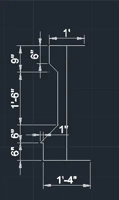
- This is the profile of the girder in the XY plan.
To dimension it first using command: D for dimension style manager , I Create a dimension style with text high 4”.
Then I change the UCS position using command: UCS, as required to dimension the element using command: DIMLIN.
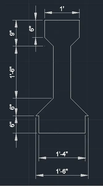
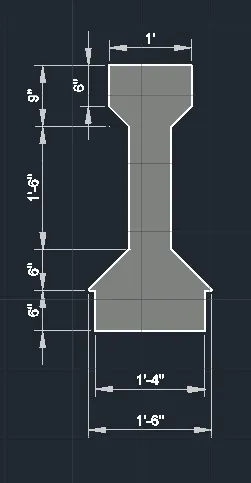
- Using command: Boundary I create a region out of the profile.
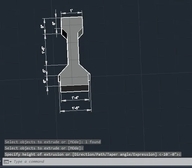
- Using command: Extrude with heigh 10’ I extrude the profile in the Z direction.
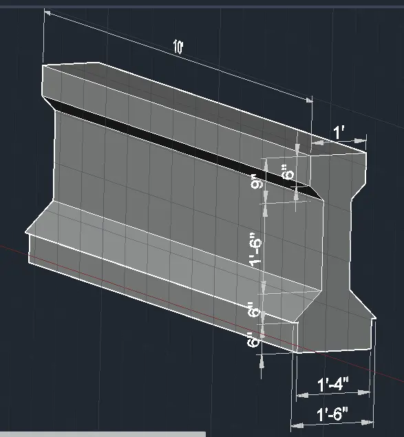
- This is the 3D view of the AASTHO Type Grider in a shade of gray in different directions.
4.Aim is to create a 3D model of a drop column with panel as shown in section and isometric view using 3D Model Workspace.
I am going to use commands: Rec, Region, Extrude, Circle, 3D Move, Loft, Presspull.
I am going to use UCS Icon, View Cube and Navigation Bar to work easily in different sides of the drawing.
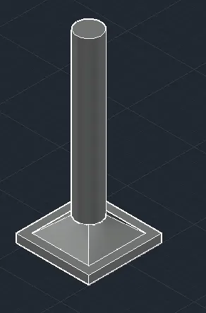
- First I draw a Rec with dim:4’6”x4’6”
I use command: Extrude to extrude the rec with heigh 6”.
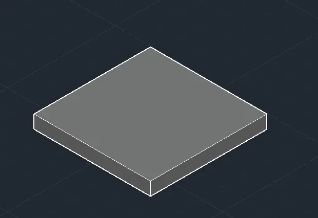
- I place the UCS in the top face of the box, draw a rec in this face and offset it with distance 6”. Then I delete the first rectang.
- In the center of the offseted rectang, I draw a circle with diameter 1’6”.
- Then using command: 3D Move I move the circle in the Z direction 1’.
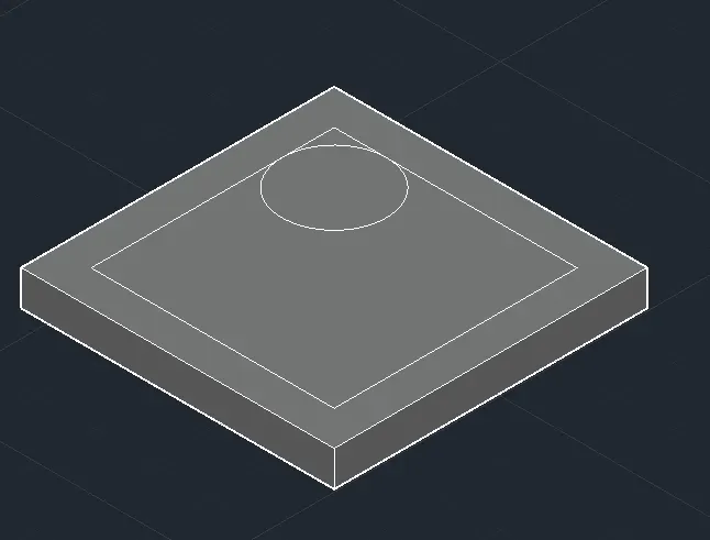
- I use command : Loft to create the element betwen rectangle and circle.
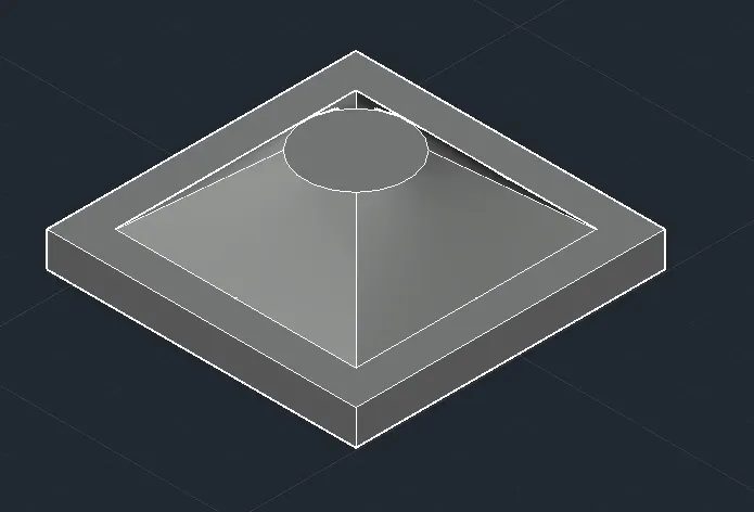
- I use command: Presspull to pull the face of the circle with a high of 10’.
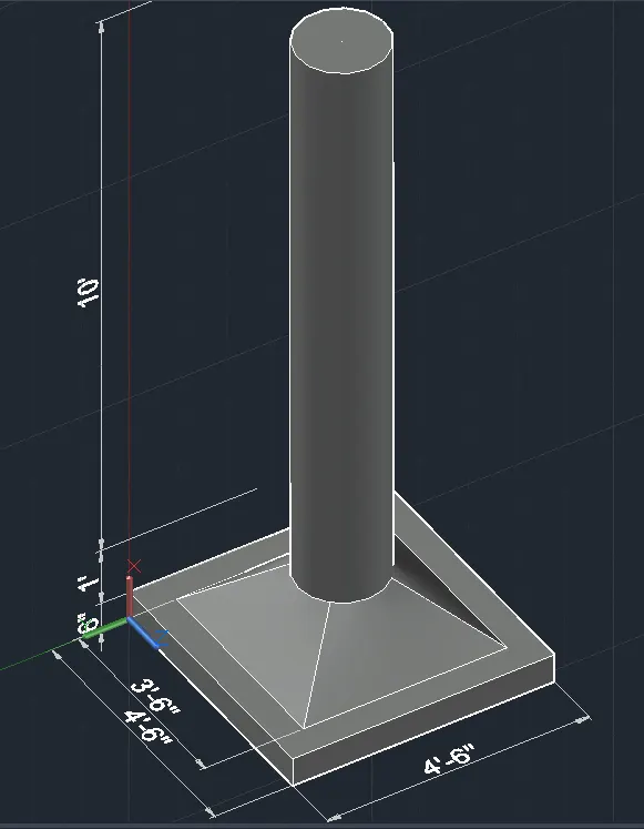
- To dimension it first using command: D for dimension style manager , I Create a dimension style with text high 4”.
Then I change the UCS position using command: UCS, as required to dimension the element using command: DIMLIN.
This is the final result of the drop column as a 3D model in a shade of gray.
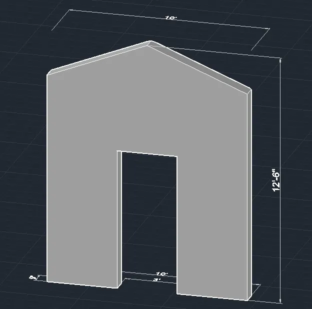
- Aim is to create a 3D model of a wall with a thickness of 9” as shown using 3D Model Workspace. I am going to use commands: Rec, explode, Region, Extrude, 3D Move, Union, Chamfer edge.
I am going to use UCS Icon, View Cube and Navigation Bar to work easily in different sides of the drawing.
- First I use command: rec to create a rec 10’x9”
Then I Explode the rec, and offset the left and right side with 3’6”.
I use command: Region to create the regions as shown.
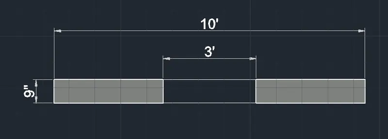
- I use command Extrude, heigh 12’6” to extrude the regions.
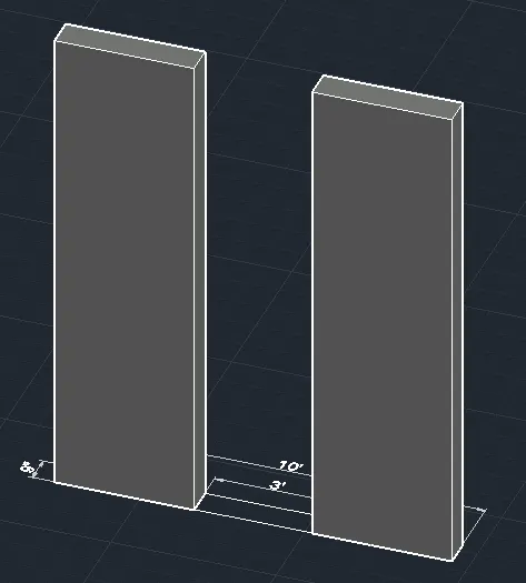
- In the space between two 3d columns, I create a rectangle, and using 3D Move I move it to the Z direction with 7’,
Then I Extrude it in the same heigh as the other two columns.
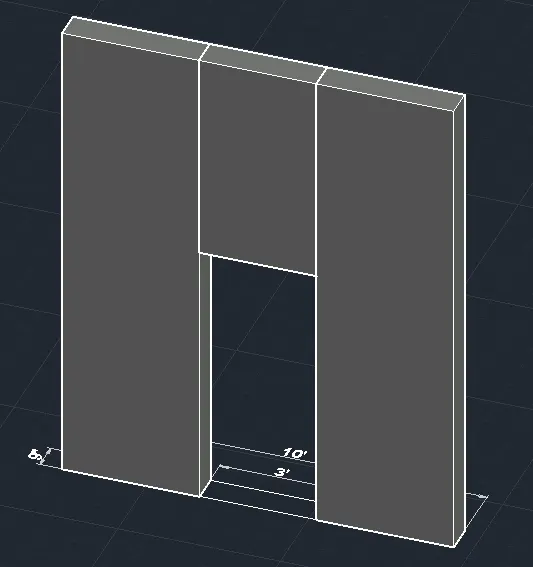
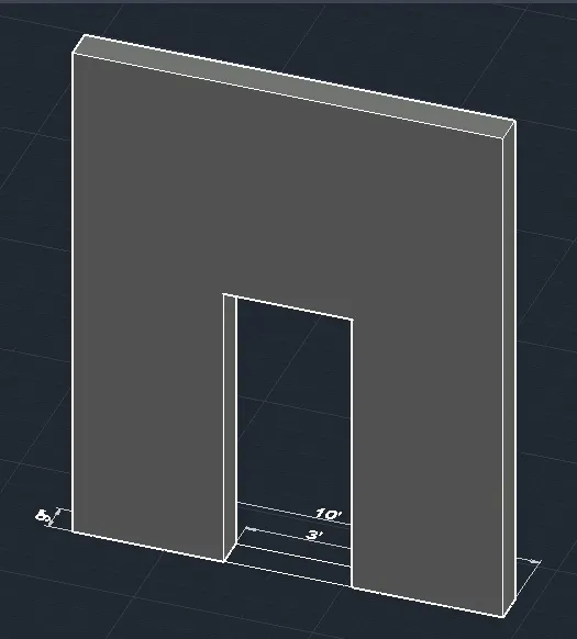
- I use command: Union to union the different parts of the wall.
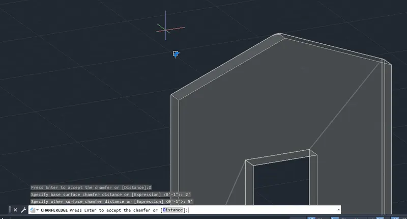
- To create the roof I use command: Chamfer Edges with distance 2’ and 5’ as shown on both top right and left edges of the wall.
- To dimension it first using command: D for dimension style manager , I Create a dimension style with text high 4”.
Then I change the UCS position using command: UCS, as required to dimension the element using command: DIMLIN.
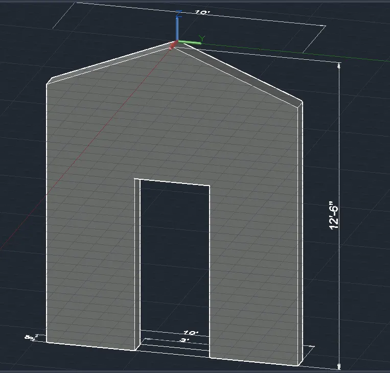
- After deleting the extra lines, This is the final result of the 3D model of the wall shaded with edge.