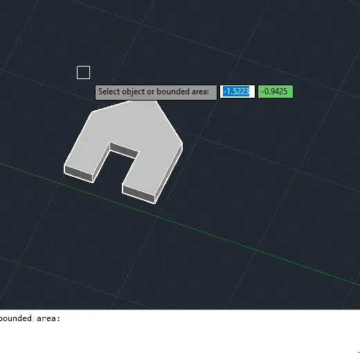
Creating various 3D Models like Furniture, Footing, Girder, Column drop with panel and Gable Wall in AutoCad
1. Aim: To Create a 3D Furniture element as shown in the Figure in autocad.
procedure: The following steps should be followed as a procedure to draw a given 3d model table using autocad
- To draw the given 3d model table in autocad, the following steps should be followed as a procedure. At first open the AutoCAD and set dimensions that the dimensions are in feets and inches.
- Then enter the Line command in AutoCAD and after that enter the first point of the given diagram as that line should be started at the point in the coordinate system.
- Then with that point draw a rectangle using rectangle command using the dimensions of the rectangle as length is 2'6" and width is 2'6".
- by using the offset command in autocad make offsset of 2' for the side of a table ie enter the dimension of the offset as 2'.
- then select the last line of the rectangle and make offset of 2.5' ie the width of the both side of a table by using the offset command in autocad.
- Open AutoCad Selecting Imperial system Command UN(units) and selecting Engineering with precision of 0’-0.0”. Command LIMITS and having limit of (0’,0’) in lower left corner and (100’,100’) in upper right corner. Command ZOOM and selecting All. Changing the Workspace from Drafting and annotation to the 3D modelling.
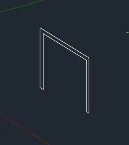
- To draw the 3d model table in autocad, the following steps should be followed as a procedure. At first open the AutoCAD and set dimensions that the dimensions are in feets and inches.
- Then enter the Line command in AutoCAD and after that enter the first point of the given diagram as that line should be started at the point in the coordinate system.
- Then with that point draw a rectangle using rectangle command using the dimensions of the rectangle as length is 2'6" and width is 2'6".
- by using the offset command in autocad make offsset of 2' for the side of a table ie enter the dimension of the offset as 2'.
- then select the last line of the rectangle and make offset of 2.5' ie the width of the both side of a table by using the offset command in autocad.
- Open AutoCad Selecting Imperial system Command UN(units) and selecting Engineering with precision of 0’-0.0”. Command LIMITS and having limit of (0’,0’) in lower left corner and (100’,100’) in upper right corner. Command ZOOM and selecting All. Changing the Workspace from Drafting and annotation to the 3D modelling.
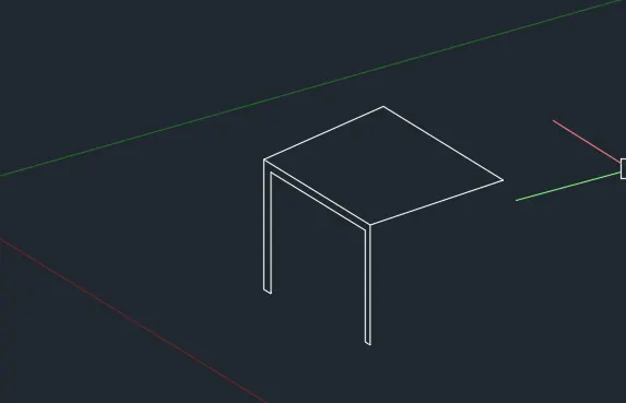
- Then enter the Line command in AutoCAD and after that enter the first point of the given diagram as that line should be started at the point in the coordinate system.
- Then with that point draw a rectangle using rectangle command using the dimensions of the rectangle as length is 2'6" and width is 2'6".
- by using the offset command in autocad make offsset of 2' for the side of a table ie enter the dimension of the offset as 2'.
- then select the last line of the rectangle and make offset of 2.5' ie the width of the both side of a table by using the offset command in autocad.
- Open AutoCad Selecting Imperial system Command UN(units) and selecting Engineering with precision of 0’-0.0”. Command LIMITS and having limit of (0’,0’) in lower left corner and (100’,100’) in upper right corner. Command ZOOM and selecting All. Changing the Workspace from Drafting and annotation to the 3D modelling.
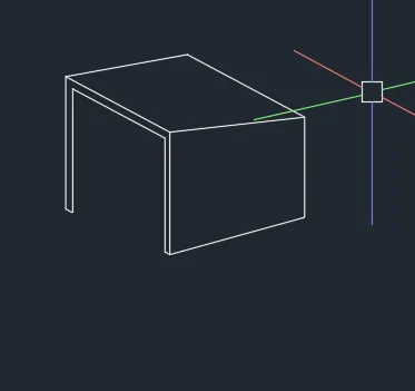
- Then enter the Line command in AutoCAD and after that enter the first point of the given diagram as that line should be started at the point in the coordinate system.
- Then with that point draw a rectangle using rectangle command using the dimensions of the rectangle as length is 2'6" and width is 2'6".
- by using the offset command in autocad make offsset of 2' for the side of a table ie enter the dimension of the offset as 2'.
- then select the last line of the rectangle and make offset of 2.5' ie the width of the both side of a table by using the offset command in autocad.
- Open AutoCad Selecting Imperial system Command UN(units) and selecting Engineering with precision of 0’-0.0”. Command LIMITS and having limit of (0’,0’) in lower left corner and (100’,100’) in upper right corner. Command ZOOM and selecting All. Changing the Workspace from Drafting and annotation to the 3D modelling.
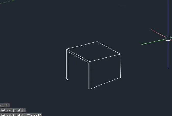
- Then enter the Line command in AutoCAD and after that enter the first point of the given diagram as that line should be started at the point in the coordinate system.
- Then with that point draw a rectangle using rectangle command using the dimensions of the rectangle as length is 2'6" and width is 2'6".
- by using the offset command in autocad make offsset of 2' for the side of a table ie enter the dimension of the offset as 2'.
- then select the last line of the rectangle and make offset of 2.5' ie the width of the both side of a table by using the offset command in autocad.
- Open AutoCad Selecting Imperial system Command UN(units) and selecting Engineering with precision of 0’-0.0”. Command LIMITS and having limit of (0’,0’) in lower left corner and (100’,100’) in upper right corner. Command ZOOM and selecting All. Changing the Workspace from Drafting and annotation to the 3D modelling.
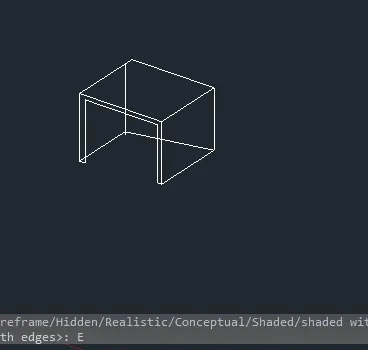
2. Aim: To Create the 3d Model of an Isolated footing as shown in Figure in autocad.
procedure: The following steps should be followed as a procedure to draw a given 3d Isolated footing using autocad.
- To draw the given 3d model table in autocad, the following steps should be followed as a procedure. At first open the AutoCAD and set dimensions that the dimensions are in feets and inches.
- Then enter the Line command in AutoCAD and after that enter the first point of the given diagram as that line should be started at the point in the coordinate system.
- Then with that point draw a rectangle using rectangle command using the dimensions of the rectangle as length is 2'6" and width is 2'6".
- by using the offset command in autocad make offsset of 2' for the side of a table ie enter the dimension of the offset as 2'.
- then select the last line of the rectangle and make offset of 2.5' ie the width of the both side of a table by using the offset command in autocad.
- Open AutoCad Selecting Imperial system Command UN(units) and selecting Engineering with precision of 0’-0.0”. Command LIMITS and having limit of (0’,0’) in lower left corner and (100’,100’) in upper right corner. Command ZOOM and selecting All. Changing the Workspace from Drafting and annotation to the 3D modelling.
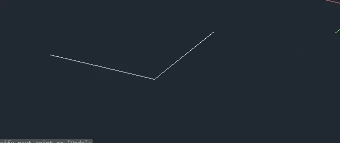
- Then with that point draw a rectangle using rectangle command using the dimensions of the rectangle as length is 2'6" and width is 2'6".
- by using the offset command in autocad make offsset of 2' for the side of a table ie enter the dimension of the offset as 2'.
- then select the last line of the rectangle and make offset of 2.5' ie the width of the both side of a table by using the offset command in autocad.
- Open AutoCad Selecting Imperial system Command UN(units) and selecting Engineering with precision of 0’-0.0”. Command LIMITS and having limit of (0’,0’) in lower left corner and (100’,100’) in upper right corner. Command ZOOM and selecting All. Changing the Workspace from Drafting and annotation to the 3D modelling.
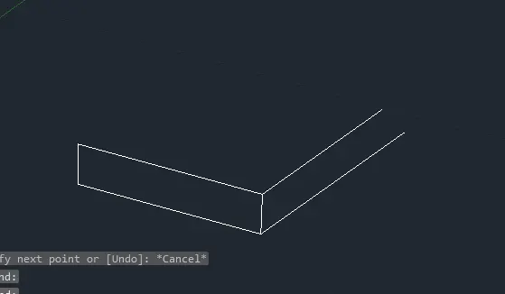
- Then enter the Line command in AutoCAD and after that enter the first point of the given diagram as that line should be started at the point in the coordinate system.
- Then with that point draw a rectangle using rectangle command using the dimensions of the rectangle as length is 2'6" and width is 2'6".
- by using the offset command in autocad make offsset of 2' for the side of a table ie enter the dimension of the offset as 2'.
- then select the last line of the rectangle and make offset of 2.5' ie the width of the both side of a table by using the offset command in autocad.
- Open AutoCad Selecting Imperial system Command UN(units) and selecting Engineering with precision of 0’-0.0”. Command LIMITS and having limit of (0’,0’) in lower left corner and (100’,100’) in upper right corner. Command ZOOM and selecting All. Changing the Workspace from Drafting and annotation to the 3D modelling.
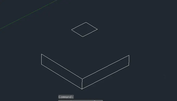
- Then with that point draw a rectangle using rectangle command using the dimensions of the rectangle as length is 2'6" and width is 2'6".
- by using the offset command in autocad make offsset of 2' for the side of a table ie enter the dimension of the offset as 2'.
- then select the last line of the rectangle and make offset of 2.5' ie the width of the both side of a table by using the offset command in autocad.
- Open AutoCad Selecting Imperial system Command UN(units) and selecting Engineering with precision of 0’-0.0”. Command LIMITS and having limit of (0’,0’) in lower left corner and (100’,100’) in upper right corner. Command ZOOM and selecting All. Changing the Workspace from Drafting and annotation to the 3D modelling.
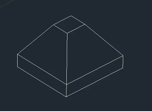
- To draw the 3d model table in autocad, the following steps should be followed as a procedure. At first open the AutoCAD and set dimensions that the dimensions are in feets and inches.
- Then enter the Line command in AutoCAD and after that enter the first point of the given diagram as that line should be started at the point in the coordinate system.
- Then with that point draw a rectangle using rectangle command using the dimensions of the rectangle as length is 2'6" and width is 2'6".
- by using the offset command in autocad make offsset of 2' for the side of a table ie enter the dimension of the offset as 2'.
- then select the last line of the rectangle and make offset of 2.5' ie the width of the both side of a table by using the offset command in autocad.
- Open AutoCad Selecting Imperial system Command UN(units) and selecting Engineering with precision of 0’-0.0”. Command LIMITS and having limit of (0’,0’) in lower left corner and (100’,100’) in upper right corner. Command ZOOM and selecting All. Changing the Workspace from Drafting and annotation to the 3D modelling.
- Then enter the Line command in AutoCAD and after that enter the first point of the given diagram as that line should be started at the point in the coordinate system.
- Then with that point draw a rectangle using rectangle command using the dimensions of the rectangle as length is 2'6" and width is 2'6".
- by using the offset command in autocad make offsset of 2' for the side of a table ie enter the dimension of the offset as 2'.
- then select the last line of the rectangle and make offset of 2.5' ie the width of the both side of a table by using the offset command in autocad.
- Open AutoCad Selecting Imperial system Command UN(units) and selecting Engineering with precision of 0’-0.0”. Command LIMITS and having limit of (0’,0’) in lower left corner and (100’,100’) in upper right corner. Command ZOOM and selecting All. Changing the Workspace from Drafting and annotation to the 3D modelling.
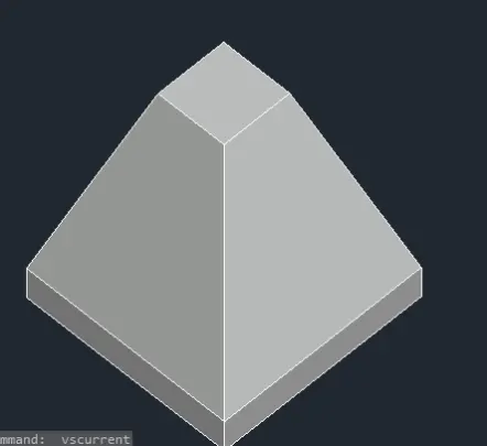
3. Aim: To Create the 3D view of the AASTHO Type Girder.
procedure: The following steps should be followed as a procedure to draw a given 3D view of the AASTHO Type Girder using autocad.
- Open AutoCad Selecting Imperial system Command UN(units) and selecting Engineering with precision of 0’-0.0” Command LIMITS and having limit of (0’,0’) in lower left corner and (100’,100’) in upper right corner Command ZOOM and selecting All Changing the Workspace from Drafting and annotation to the 3D modelling.
- To draw the given 3d model table in autocad, the following steps should be followed as a procedure. At first open the AutoCAD and set dimensions that the dimensions are in feets and inches.
- Then enter the Line command in AutoCAD and after that enter the first point of the given diagram as that line should be started at the point in the coordinate system.
- Then with that point draw a rectangle using rectangle command using the dimensions of the rectangle as length is 2'6" and width is 2'6".
- by using the offset command in autocad make offsset of 2' for the side of a table ie enter the dimension of the offset as 2'.
- then select the last line of the rectangle and make offset of 2.5' ie the width of the both side of a table by using the offset command in autocad.
- Open AutoCad Selecting Imperial system Command UN(units) and selecting Engineering with precision of 0’-0.0”. Command LIMITS and having limit of (0’,0’) in lower left corner and (100’,100’) in upper right corner. Command ZOOM and selecting All. Changing the Workspace from Drafting and annotation to the 3D modelling.
- Then with that point draw a rectangle using rectangle command using the dimensions of the rectangle as length is 2'6" and width is 2'6".
- by using the offset command in autocad make offsset of 2' for the side of a table ie enter the dimension of the offset as 2'.
- then select the last line of the rectangle and make offset of 2.5' ie the width of the both side of a table by using the offset command in autocad.
- Open AutoCad Selecting Imperial system Command UN(units) and selecting Engineering with precision of 0’-0.0”. Command LIMITS and having limit of (0’,0’) in lower left corner and (100’,100’) in upper right corner. Command ZOOM and selecting All. Changing the Workspace from Drafting and annotation to the 3D modelling.
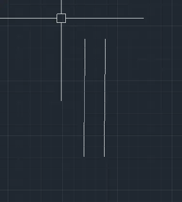
- To draw the 3d model table in autocad, the following steps should be followed as a procedure. At first open the AutoCAD and set dimensions that the dimensions are in feets and inches.
- Then enter the Line command in AutoCAD and after that enter the first point of the given diagram as that line should be started at the point in the coordinate system.
- Then with that point draw a rectangle using rectangle command using the dimensions of the rectangle as length is 2'6" and width is 2'6".
- by using the offset command in autocad make offsset of 2' for the side of a table ie enter the dimension of the offset as 2'.
- then select the last line of the rectangle and make offset of 2.5' ie the width of the both side of a table by using the offset command in autocad.
- Open AutoCad Selecting Imperial system Command UN(units) and selecting Engineering with precision of 0’-0.0”. Command LIMITS and having limit of (0’,0’) in lower left corner and (100’,100’) in upper right corner. Command ZOOM and selecting All. Changing the Workspace from Drafting and annotation to the 3D modelling.
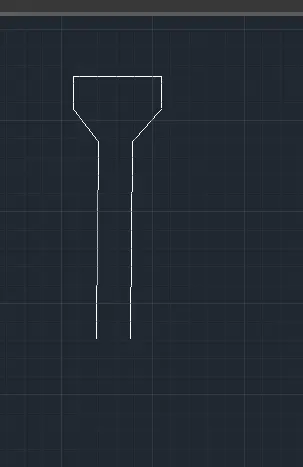
- Then with that point draw a rectangle using rectangle command using the dimensions of the rectangle as length is 2'6" and width is 2'6".
- by using the offset command in autocad make offsset of 2' for the side of a table ie enter the dimension of the offset as 2'.
- then select the last line of the rectangle and make offset of 2.5' ie the width of the both side of a table by using the offset command in autocad.
- Open AutoCad Selecting Imperial system Command UN(units) and selecting Engineering with precision of 0’-0.0”. Command LIMITS and having limit of (0’,0’) in lower left corner and (100’,100’) in upper right corner. Command ZOOM and selecting All. Changing the Workspace from Drafting and annotation to the 3D modelling.
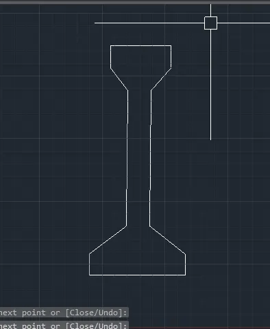
- To draw the 3d model table in autocad, the following steps should be followed as a procedure. At first open the AutoCAD and set dimensions that the dimensions are in feets and inches.
- Then enter the Line command in AutoCAD and after that enter the first point of the given diagram as that line should be started at the point in the coordinate system.
- Then with that point draw a rectangle using rectangle command using the dimensions of the rectangle as length is 2'6" and width is 2'6".
- by using the offset command in autocad make offsset of 2' for the side of a table ie enter the dimension of the offset as 2'.
- then select the last line of the rectangle and make offset of 2.5' ie the width of the both side of a table by using the offset command in autocad.
- Open AutoCad Selecting Imperial system Command UN(units) and selecting Engineering with precision of 0’-0.0”. Command LIMITS and having limit of (0’,0’) in lower left corner and (100’,100’) in upper right corner. Command ZOOM and selecting All. Changing the Workspace from Drafting and annotation to the 3D modelling.
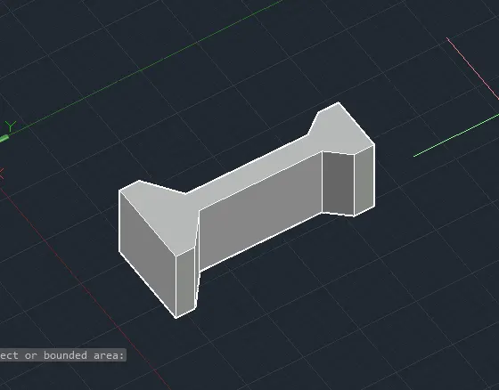
4. Aim: To create Create a 3d Model of a drop column with panel as shown in section and isometric view.
procedure: The following steps should be followed as a procedure to draw a given 3d Model of a drop column with panel as shown in section and isometric view autocad.
- To draw the given 3d model table in autocad, the following steps should be followed as a procedure. At first open the AutoCAD and set dimensions that the dimensions are in feets and inches.
- Then enter the Line command in AutoCAD and after that enter the first point of the given diagram as that line should be started at the point in the coordinate system.
- Then with that point draw a rectangle using rectangle command using the dimensions of the rectangle as length is 2'6" and width is 2'6".
- by using the offset command in autocad make offsset of 2' for the side of a table ie enter the dimension of the offset as 2'.
- then select the last line of the rectangle and make offset of 2.5' ie the width of the both side of a table by using the offset command in autocad.
- Open AutoCad Selecting Imperial system Command UN(units) and selecting Engineering with precision of 0’-0.0”. Command LIMITS and having limit of (0’,0’) in lower left corner and (100’,100’) in upper right corner. Command ZOOM and selecting All. Changing the Workspace from Drafting and annotation to the 3D modelling.
- Open AutoCad Selecting Imperial system Command UN(units) and selecting Engineering with precision of 0’-0.0” Command LIMITS and having limit of (0’,0’) in lower left corner and (100’,100’) in upper right corner Command ZOOM and selecting Al.
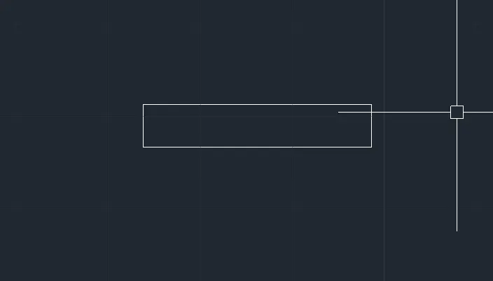
- Then with that point draw a rectangle using rectangle command using the dimensions of the rectangle as length is 2'6" and width is 2'6".
- by using the offset command in autocad make offsset of 2' for the side of a table ie enter the dimension of the offset as 2'.
- then select the last line of the rectangle and make offset of 2.5' ie the width of the both side of a table by using the offset command in autocad.
- Open AutoCad Selecting Imperial system Command UN(units) and selecting Engineering with precision of 0’-0.0”. Command LIMITS and having limit of (0’,0’) in lower left corner and (100’,100’) in upper right corner. Command ZOOM and selecting All. Changing the Workspace from Drafting and annotation to the 3D modelling.
- Then with that point draw a rectangle using rectangle command using the dimensions of the rectangle as length is 2'6" and width is 2'6".
- by using the offset command in autocad make offsset of 2' for the side of a table ie enter the dimension of the offset as 2'.
- then select the last line of the rectangle and make offset of 2.5' ie the width of the both side of a table by using the offset command in autocad.
- Open AutoCad Selecting Imperial system Command UN(units) and selecting Engineering with precision of 0’-0.0”. Command LIMITS and having limit of (0’,0’) in lower left corner and (100’,100’) in upper right corner. Command ZOOM and selecting All. Changing the Workspace from Drafting and annotation to the 3D modelling.
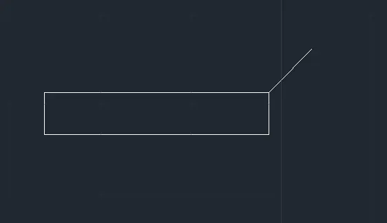
- To draw the 3d model table in autocad, the following steps should be followed as a procedure. At first open the AutoCAD and set dimensions that the dimensions are in feets and inches.
- Then enter the Line command in AutoCAD and after that enter the first point of the given diagram as that line should be started at the point in the coordinate system.
- Then with that point draw a rectangle using rectangle command using the dimensions of the rectangle as length is 2'6" and width is 2'6".
- by using the offset command in autocad make offsset of 2' for the side of a table ie enter the dimension of the offset as 2'.
- then select the last line of the rectangle and make offset of 2.5' ie the width of the both side of a table by using the offset command in autocad.
- Open AutoCad Selecting Imperial system Command UN(units) and selecting Engineering with precision of 0’-0.0”. Command LIMITS and having limit of (0’,0’) in lower left corner and (100’,100’) in upper right corner. Command ZOOM and selecting All. Changing the Workspace from Drafting and annotation to the 3D modelling.

- To draw the 3d model table in autocad, the following steps should be followed as a procedure. At first open the AutoCAD and set dimensions that the dimensions are in feets and inches.
- Then enter the Line command in AutoCAD and after that enter the first point of the given diagram as that line should be started at the point in the coordinate system.
- Then with that point draw a rectangle using rectangle command using the dimensions of the rectangle as length is 2'6" and width is 2'6".
- by using the offset command in autocad make offsset of 2' for the side of a table ie enter the dimension of the offset as 2'.
- then select the last line of the rectangle and make offset of 2.5' ie the width of the both side of a table by using the offset command in autocad.
- Open AutoCad Selecting Imperial system Command UN(units) and selecting Engineering with precision of 0’-0.0”. Command LIMITS and having limit of (0’,0’) in lower left corner and (100’,100’) in upper right corner. Command ZOOM and selecting All. Changing the Workspace from Drafting and annotation to the 3D modelling.
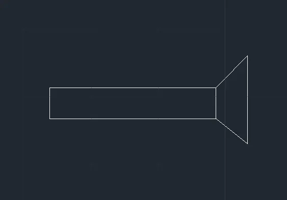
- To draw the 3d model table in autocad, the following steps should be followed as a procedure. At first open the AutoCAD and set dimensions that the dimensions are in feets and inches.
- Then enter the Line command in AutoCAD and after that enter the first point of the given diagram as that line should be started at the point in the coordinate system.
- Then with that point draw a rectangle using rectangle command using the dimensions of the rectangle as length is 2'6" and width is 2'6".
- by using the offset command in autocad make offsset of 2' for the side of a table ie enter the dimension of the offset as 2'.
- then select the last line of the rectangle and make offset of 2.5' ie the width of the both side of a table by using the offset command in autocad.
- Open AutoCad Selecting Imperial system Command UN(units) and selecting Engineering with precision of 0’-0.0”. Command LIMITS and having limit of (0’,0’) in lower left corner and (100’,100’) in upper right corner. Command ZOOM and selecting All. Changing the Workspace from Drafting and annotation to the 3D modelling.
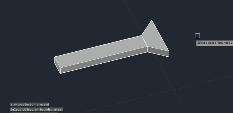
- To draw the 3d model table in autocad, the following steps should be followed as a procedure. At first open the AutoCAD and set dimensions that the dimensions are in feets and inches.
- Then enter the Line command in AutoCAD and after that enter the first point of the given diagram as that line should be started at the point in the coordinate system.
- Then with that point draw a rectangle using rectangle command using the dimensions of the rectangle as length is 2'6" and width is 2'6".
- by using the offset command in autocad make offsset of 2' for the side of a table ie enter the dimension of the offset as 2'.
- then select the last line of the rectangle and make offset of 2.5' ie the width of the both side of a table by using the offset command in autocad.
- Open AutoCad Selecting Imperial system Command UN(units) and selecting Engineering with precision of 0’-0.0”. Command LIMITS and having limit of (0’,0’) in lower left corner and (100’,100’) in upper right corner. Command ZOOM and selecting All. Changing the Workspace from Drafting and annotation to the 3D modelling.
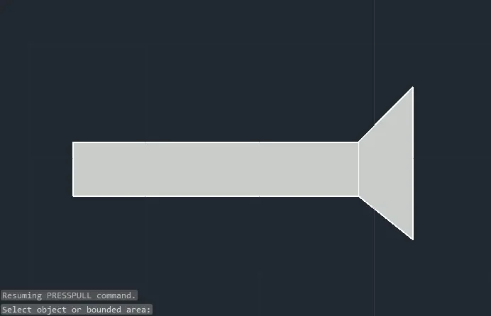
- To draw the 3d model table in autocad, the following steps should be followed as a procedure. At first open the AutoCAD and set dimensions that the dimensions are in feets and inches.
- Then enter the Line command in AutoCAD and after that enter the first point of the given diagram as that line should be started at the point in the coordinate system.
- Then with that point draw a rectangle using rectangle command using the dimensions of the rectangle as length is 2'6" and width is 2'6".
- by using the offset command in autocad make offsset of 2' for the side of a table ie enter the dimension of the offset as 2'.
- then select the last line of the rectangle and make offset of 2.5' ie the width of the both side of a table by using the offset command in autocad.
- Open AutoCad Selecting Imperial system Command UN(units) and selecting Engineering with precision of 0’-0.0”. Command LIMITS and having limit of (0’,0’) in lower left corner and (100’,100’) in upper right corner. Command ZOOM and selecting All. Changing the Workspace from Drafting and annotation to the 3D modelling.
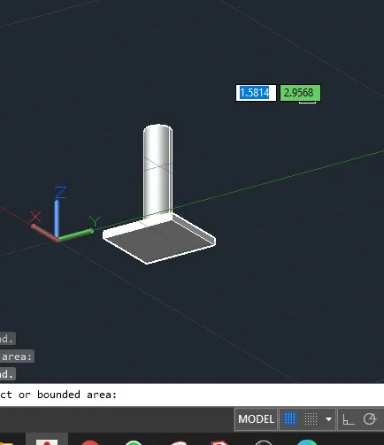
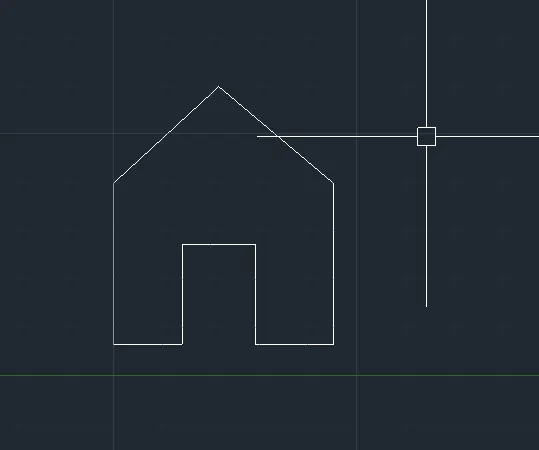
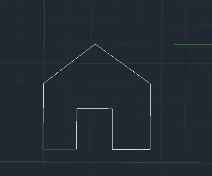
5. Aim: To Create the 3d model of a wall as shown in Figure. Considering the wall thickness as 9”.
procedure: The following steps should be followed as a procedure to draw a given 3d model of a wall as shown in Figure as shown in section and isometric view autocad.
- To draw the given 3d model table in autocad, the following steps should be followed as a procedure. At first open the AutoCAD and set dimensions that the dimensions are in feets and inches.
- Then enter the Line command in AutoCAD and after that enter the first point of the given diagram as that line should be started at the point in the coordinate system.
- Then with that point draw a rectangle using rectangle command using the dimensions of the rectangle as length is 2'6" and width is 2'6".
- by using the offset command in autocad make offsset of 2' for the side of a table ie enter the dimension of the offset as 2'.
- then select the last line of the rectangle and make offset of 2.5' ie the width of the both side of a table by using the offset command in autocad.
- Open AutoCad Selecting Imperial system Command UN(units) and selecting Engineering with precision of 0’-0.0” Command LIMITS and having limit of (0’,0’) in lower left corner and (100’,100’) in upper right corner Command ZOOM and selecting All Changing the Workspace from Drafting and annotation to the 3D modelling.
- by using the offset command in autocad make offsset of 2' for the side of a table ie enter the dimension of the offset as 2'.
- then select the last line of the rectangle and make offset of 2.5' ie the width of the both side of a table by using the offset command in autocad.
- Open AutoCad Selecting Imperial system Command UN(units) and selecting Engineering with precision of 0’-0.0” Command LIMITS and having limit of (0’,0’) in lower left corner and (100’,100’) in upper right corner Command ZOOM and selecting All Changing the Workspace from Drafting and annotation to the 3D modelling
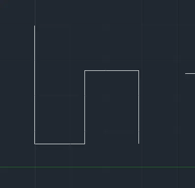
- Then with that point draw a rectangle using rectangle command using the dimensions of the rectangle as length is 2'6" and width is 2'6".
- by using the offset command in autocad make offsset of 2' for the side of a table ie enter the dimension of the offset as 2'.
- then select the last line of the rectangle and make offset of 2.5' ie the width of the both side of a table by using the offset command in autocad.
- Open AutoCad Selecting Imperial system Command UN(units) and selecting Engineering with precision of 0’-0.0”. Command LIMITS and having limit of (0’,0’) in lower left corner and (100’,100’) in upper right corner. Command ZOOM and selecting All. Changing the Workspace from Drafting and annotation to the 3D modelling.
- Then with that point draw a rectangle using rectangle command using the dimensions of the rectangle as length is 2'6" and width is 2'6".
- by using the offset command in autocad make offsset of 2' for the side of a table ie enter the dimension of the offset as 2'.
- then select the last line of the rectangle and make offset of 2.5' ie the width of the both side of a table by using the offset command in autocad.
- Open AutoCad Selecting Imperial system Command UN(units) and selecting Engineering with precision of 0’-0.0”. Command LIMITS and having limit of (0’,0’) in lower left corner and (100’,100’) in upper right corner. Command ZOOM and selecting All. Changing the Workspace from Drafting and annotation to the 3D modelling.
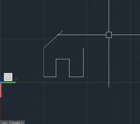
- To draw the 3d model table in autocad, the following steps should be followed as a procedure. At first open the AutoCAD and set dimensions that the dimensions are in feets and inches.
- Then enter the Line command in AutoCAD and after that enter the first point of the given diagram as that line should be started at the point in the coordinate system.
- Then with that point draw a rectangle using rectangle command using the dimensions of the rectangle as length is 2'6" and width is 2'6".
- by using the offset command in autocad make offsset of 2' for the side of a table ie enter the dimension of the offset as 2'.
- then select the last line of the rectangle and make offset of 2.5' ie the width of the both side of a table by using the offset command in autocad.
- Open AutoCad Selecting Imperial system Command UN(units) and selecting Engineering with precision of 0’-0.0”. Command LIMITS and having limit of (0’,0’) in lower left corner and (100’,100’) in upper right corner. Command ZOOM and selecting All. Changing the Workspace from Drafting and annotation to the 3D modelling.
- To draw the 3d model table in autocad, the following steps should be followed as a procedure. At first open the AutoCAD and set dimensions that the dimensions are in feets and inches.
- Then enter the Line command in AutoCAD and after that enter the first point of the given diagram as that line should be started at the point in the coordinate system.
- Then with that point draw a rectangle using rectangle command using the dimensions of the rectangle as length is 2'6" and width is 2'6".
- by using the offset command in autocad make offsset of 2' for the side of a table ie enter the dimension of the offset as 2'.
- then select the last line of the rectangle and make offset of 2.5' ie the width of the both side of a table by using the offset command in autocad.
- Open AutoCad Selecting Imperial system Command UN(units) and selecting Engineering with precision of 0’-0.0”. Command LIMITS and having limit of (0’,0’) in lower left corner and (100’,100’) in upper right corner. Command ZOOM and selecting All. Changing the Workspace from Drafting and annotation to the 3D modelling.
- To draw the 3d model table in autocad, the following steps should be followed as a procedure. At first open the AutoCAD and set dimensions that the dimensions are in feets and inches.
- Then enter the Line command in AutoCAD and after that enter the first point of the given diagram as that line should be started at the point in the coordinate system.
- Then with that point draw a rectangle using rectangle command using the dimensions of the rectangle as length is 2'6" and width is 2'6".
- by using the offset command in autocad make offsset of 2' for the side of a table ie enter the dimension of the offset as 2'.
- then select the last line of the rectangle and make offset of 2.5' ie the width of the both side of a table by using the offset command in autocad.
- Open AutoCad Selecting Imperial system Command UN(units) and selecting Engineering with precision of 0’-0.0”. Command LIMITS and having limit of (0’,0’) in lower left corner and (100’,100’) in upper right corner. Command ZOOM and selecting All. Changing the Workspace from Drafting and annotation to the 3D modelling.
- To draw the 3d model table in autocad, the following steps should be followed as a procedure. At first open the AutoCAD and set dimensions that the dimensions are in feets and inches.
- Then enter the Line command in AutoCAD and after that enter the first point of the given diagram as that line should be started at the point in the coordinate system.
- Then with that point draw a rectangle using rectangle command using the dimensions of the rectangle as length is 2'6" and width is 2'6".
- by using the offset command in autocad make offsset of 2' for the side of a table ie enter the dimension of the offset as 2'.
- then select the last line of the rectangle and make offset of 2.5' ie the width of the both side of a table by using the offset command in autocad.
- Open AutoCad Selecting Imperial system Command UN(units) and selecting Engineering with precision of 0’-0.0”. Command LIMITS and having limit of (0’,0’) in lower left corner and (100’,100’) in upper right corner. Command ZOOM and selecting All. Changing the Workspace from Drafting and annotation to the 3D modelling.