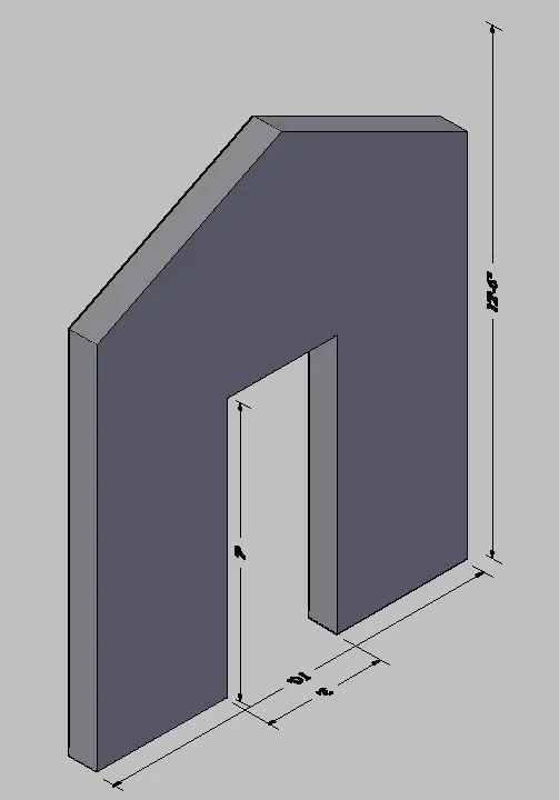
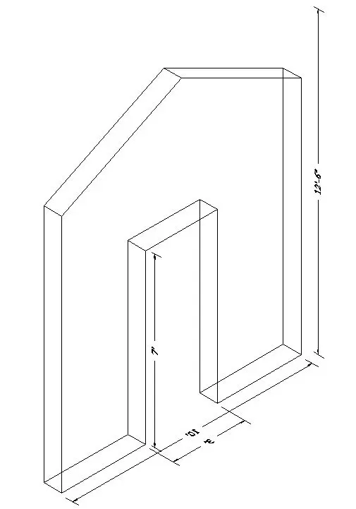
Creating various 3D Models like Furniture, Footing, Girder, Column drop with panel and Gable Wall in AutoCad
Creating various 3D Models like Furniture, Footing, Girder, Column drop with panel and Gable Wall in AutoCad
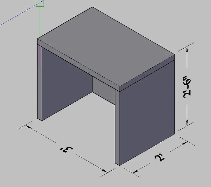
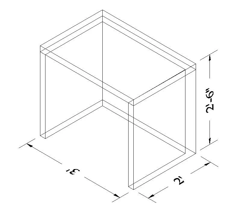
1. Create a 3D Furniture element as shown in the Figure. Assume dimensions which are missing
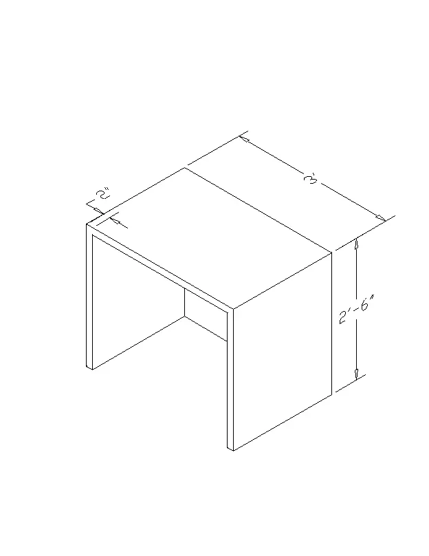
Aim: To create a 3D Furniture element using AutoCAD software.
Commands Used:
| Command name | Command Shortcut | Command Use |
| Units | UN | To change Units suitable to your Project. |
| Line | L | Used to Create a Line. |
| Poly Line | PL | Used to Create a Ploy Line. |
| Rectangle | REC | Used to Create a Rectangle. |
| Extrude | EXTRUDE | Used to change Object 2D to 3D. |
| Dimension Linear | DLI | Used to give Dimension to Object. |
| Dimension Diameter | DDI | Used to give Diameter Dimension to Object. |
| Fillet | F | Used to change object edges to Smooth. |
| Zoom | Z | Used to Zoom object in sheet |
| Zoom for Exist sheet | Z (Enter) & E (Enter) | Used to Zoom the object and Fit to sheet. |
Procedure:
- First of all open autocad software and create a new sheet which is suitable to our project.
- change the unit according to work like change metric to imperial.
- Use Poly-Line PL Command Draw line.
- Use Extrude Command to the blocked object according to recpective dimensions.
- Use DLI Dimension Linear Command to give dimension to Object.
- To give Dimension in vertical direction change the face of object and give dimension using the DLI command.
- Go to Layout Rename the Layout name using Zoom Z Command Fit the object to sheet.
Project Images:
2. Create the 3d Model of an Isolated footing as shown in Figure.
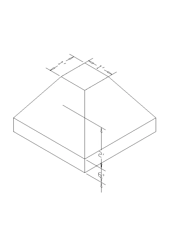
Aim: To create the 3D model of an isolated footing using AutoCAD software.
Commands Used:
| Command name | Command Shortcut | Command Use |
| Units | UN | To change Units suitable to your Project. |
| Line | L | Used to Create a Line. |
| Poly Line | PL | Used to Create a Ploy Line. |
| Rectangle | REC | Used to Create a Rectangle. |
| Extrude | EXTRUDE | Used to change Object 2D to 3D. |
| Dimension Linear | DLI | Used to give Dimension to Object. |
| Dimension Diameter | DDI | Used to give Diameter Dimension to Object. |
| Fillet | F | Used to change object edges to Smooth. |
| Zoom | Z | Used to Zoom object in sheet |
| Zoom for Exist sheet | Z (Enter) & E (Enter) | Used to Zoom the object and Fit to sheet. |
Procedure:
- First of all open autocad software and create a new sheet which is suitable to our project.
- change the unit according to work like change metric to imperial.
- Use Poly-Line PL Command Draw line.
- Use Extrude Command to the blocked object according to recpective dimensions.
- Use DLI Dimension Linear Command to give dimension to Object.
- To give Dimension in vertical direction change the face of object and give dimension using the DLI command.
- Go to Layout Rename the Layout name using Zoom Z Command Fit the object to sheet.
Project Images:
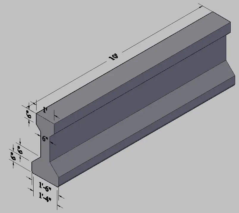
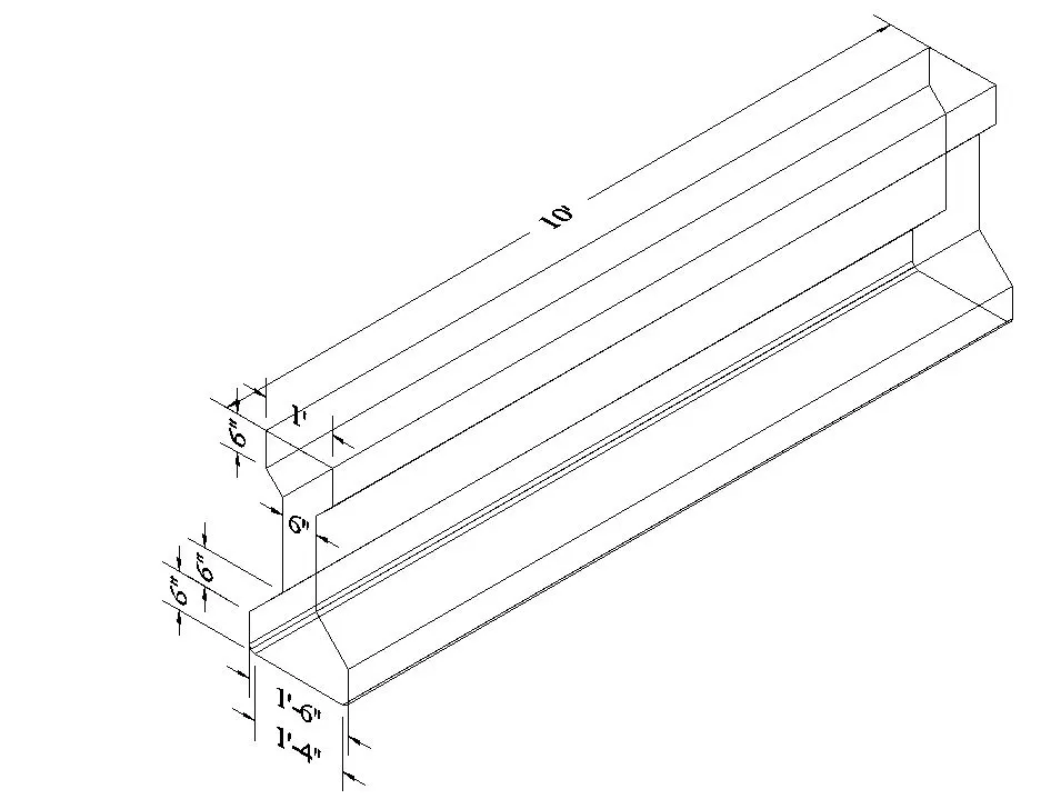
3. Create the 3D view of the AASTHO Type Girder.
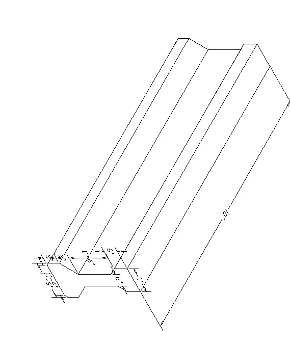
Aim: To create the 3D view of the AASTHO Type Girder using AutoCAD software.
Commands Used:
| Command name | Command Shortcut | Command Use |
| Units | UN | To change Units suitable to your Project. |
| Line | L | Used to Create a Line. |
| Poly Line | PL | Used to Create a Ploy Line. |
| Rectangle | REC | Used to Create a Rectangle. |
| Extrude | EXTRUDE | Used to change Object 2D to 3D. |
| Dimension Linear | DLI | Used to give Dimension to Object. |
| Dimension Diameter | DDI | Used to give Diameter Dimension to Object. |
| Fillet | F | Used to change object edges to Smooth. |
| Zoom | Z | Used to Zoom object in sheet |
| Zoom for Exist sheet | Z (Enter) & E (Enter) | Used to Zoom the object and Fit to sheet. |
Procedure:
- First of all open autocad software and create a new sheet which is suitable to our project.
- change the unit according to work like change metric to imperial.
- Use Poly-Line PL Command Draw line.
- Use Extrude Command to the blocked object according to recpective dimensions.
- Use DLI Dimension Linear Command to give dimension to Object.
- To give Dimension in vertical direction change the face of object and give dimension using the DLI command.
- Go to Layout Rename the Layout name using Zoom Z Command Fit the object to sheet.
Project Images:
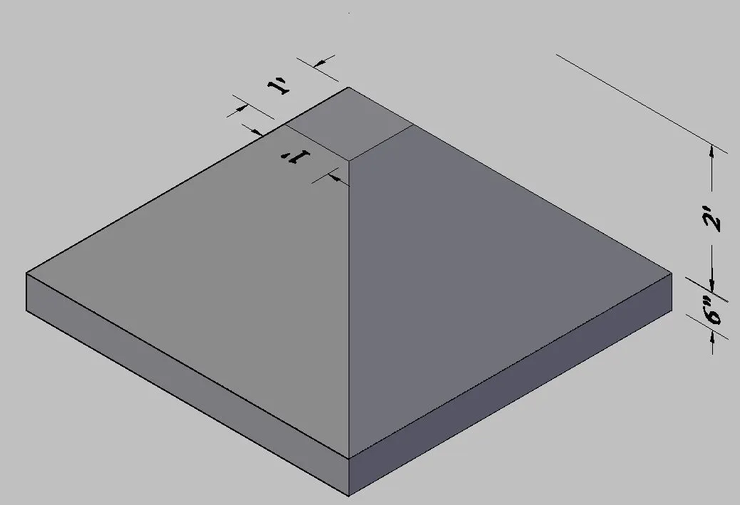
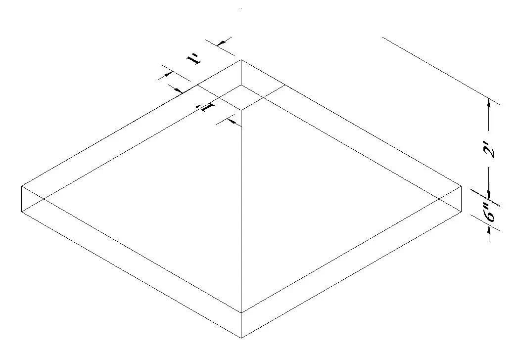
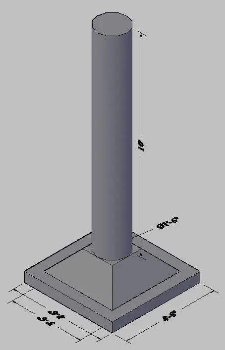
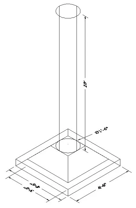
4. Create a 3d Model of a drop column with panel as shown in section and isometric view.
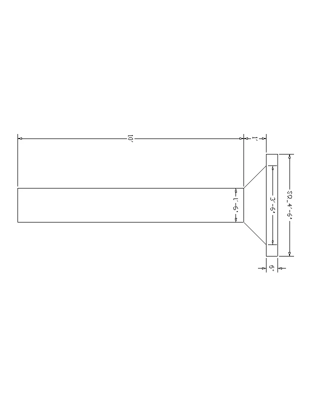
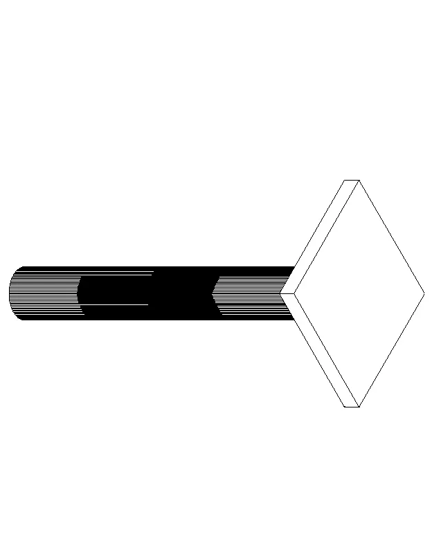
Aim: To create a 3d Model of a drop column with panel using AutoCAD software.
Commands Used:
| Command name | Command Shortcut | Command Use |
| Units | UN | To change Units suitable to your Project. |
| Line | L | Used to Create a Line. |
| Poly Line | PL | Used to Create a Ploy Line. |
| Rectangle | REC | Used to Create a Rectangle. |
| Extrude | EXTRUDE | Used to change Object 2D to 3D. |
| Dimension Linear | DLI | Used to give Dimension to Object. |
| Dimension Diameter | DDI | Used to give Diameter Dimension to Object. |
| Fillet | F | Used to change object edges to Smooth. |
| Zoom | Z | Used to Zoom object in sheet |
| Zoom for Exist sheet | Z (Enter) & E (Enter) | Used to Zoom the object and Fit to sheet. |
Procedure:
- First of all open autocad software and create a new sheet which is suitable to our project.
- change the unit according to work like change metric to imperial.
- Use Poly-Line PL Command Draw line.
- Use Extrude Command to the blocked object according to recpective dimensions.
- Use DLI Dimension Linear Command to give dimension to Object.
- To give Dimension in vertical direction change the face of object and give dimension using the DLI command.
- Go to Layout Rename the Layout name using Zoom Z Command Fit the object to sheet.
Project Images:
5. Create the 3d model of a wall as shown in Figure. Consider wall thickness as 9”.
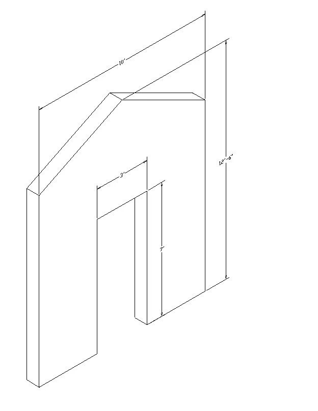
Aim: To create the 3d model of a wall using AutoCAD software.
Commands Used:
| Command name | Command Shortcut | Command Use |
| Units | UN | To change Units suitable to your Project. |
| Line | L | Used to Create a Line. |
| Poly Line | PL | Used to Create a Ploy Line. |
| Rectangle | REC | Used to Create a Rectangle. |
| Extrude | EXTRUDE | Used to change Object 2D to 3D. |
| Dimension Linear | DLI | Used to give Dimension to Object. |
| Dimension Diameter | DDI | Used to give Diameter Dimension to Object. |
| Fillet | F | Used to change object edges to Smooth. |
| Zoom | Z | Used to Zoom object in sheet |
| Zoom for Exist sheet | Z (Enter) & E (Enter) | Used to Zoom the object and Fit to sheet. |
Procedure:
- First of all open autocad software and create a new sheet which is suitable to our project.
- change the unit according to work like change metric to imperial.
- Use Poly-Line PL Command Draw line.
- Use Extrude Command to the blocked object according to recpective dimensions.
- Use DLI Dimension Linear Command to give dimension to Object.
- To give Dimension in vertical direction change the face of object and give dimension using the DLI command.
- Go to Layout Rename the Layout name using Zoom Z Command Fit the object to sheet.
Project Images: