Creating various 3D Models like Furniture, Footing, Girder, Column drop with panel and Gable Wall in AutoCad
AIM :
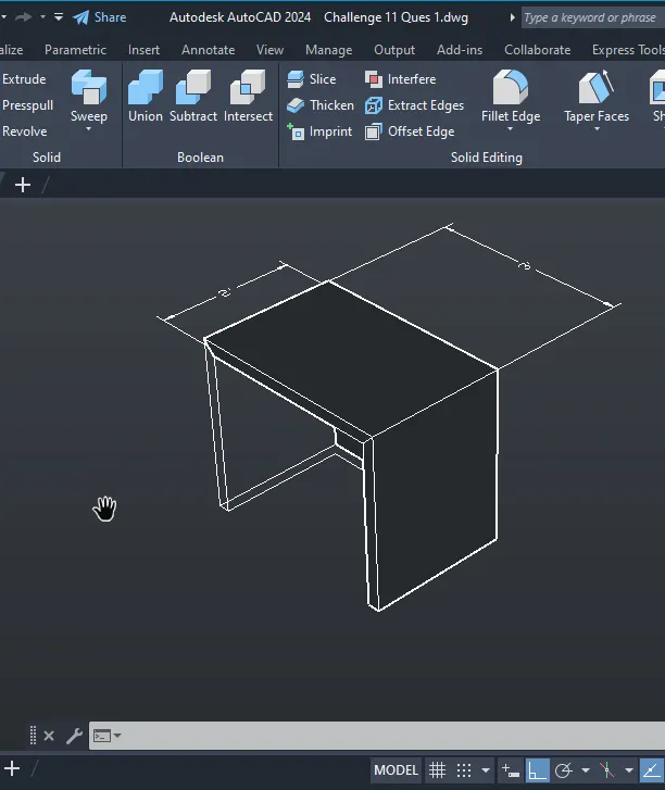
1. Create a 3D Furniture element as shown in the Figure. Assume dimensions which are missing
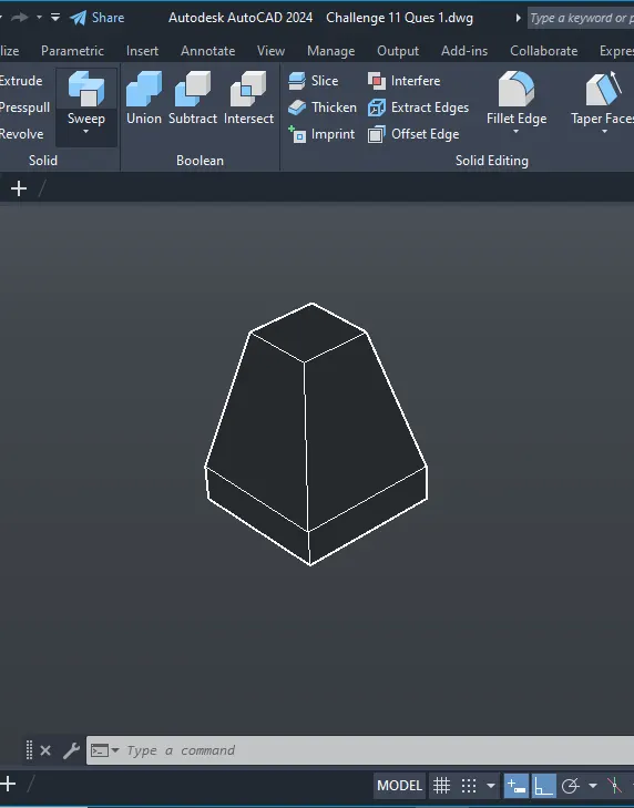
2. Create the 3d Model of an Isolated footing as shown in Figure
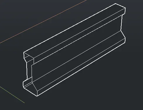
3. Create the 3D view of the AASTHO Type Girder
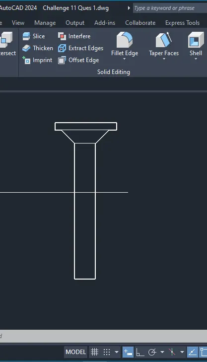
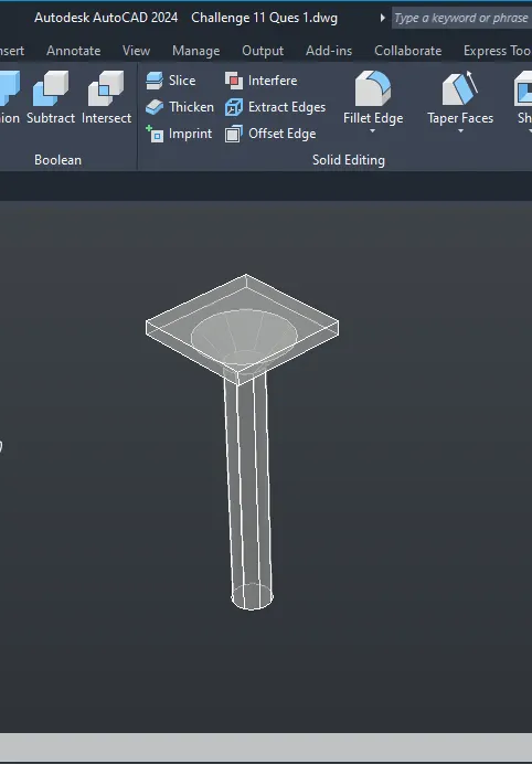
4. Create a 3d Model of a drop column with panel as shown in section and isometric view
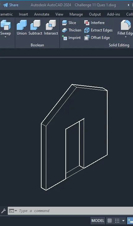
5. Create the 3d model of a wall as shown in Figure. Consider wall thickness as 9”
INTRODUCTION :
3-D : A way of displaying real-world object in a more natural way by adding depth to the height and width. This system uses the X Y and Z axes.
Elevation : The difference between an object being at zero on the Z-axis and the height that it is above zero.
Extrude : Draw > Modeling > Extrude ,The extrude command raises the shape of a 2D outline into a 3D solid. For example, a circle would be extruded into a cylinder. (Extrude)
Hidden line removal : A way of hiding lines that would not be visible if you were viewing the actual object you have drawn in AutoCAD. (Command: HIDE)
Wire Framed Model : A 3-D shape that is defined by lines and curves. A skeletal representation. Hidden line removal is not possible with this model.
Surface Model : A 3-D model defined by surfaces. The surface consists of polygons.
Solid Model : A 3-D model creating using solid 'building blocks'. This is the most accurate way of representing real-world objects in CAD.
Sweep : Draw > Modeling > Sweep ,This command helps the user to extrude the 2D objects without the 2D face being orthogonal to the beginning of the path.
Union : Modify > Solids Editing > Union ,This AutoCAD 3D command allows the user to combine two objects converting them into one single object.
Suntract : Modify > Solids Editing > Subtract ,This command is opposite to the union command; this command works when there is a common area in both the objects. Then this command subtracts the object A from the object B.
Intersect: Modify > Solid Editing > Intersect ,With this AutoCAD 3D command, the user is left with the area that is common to both the objects.
UCS : The user co-ordinate system. This is defined by the person drawing to have easier access to portions of a 3-D model.
SolidEdits : Edits faces and edges of 3D solid objects. You can extrude, move, rotate, offset, taper, copy, delete, and assign colors and materials to faces. You can also copy and assign colors to edges. You can imprint, separate, shell, clean, and check the validity of the entire 3D solid object (body). You cannot use SOLIDEDIT with mesh objects. However, if you select a closed mesh object, you will be prompted to convert it to a 3D solid
PROCEDURE :
1. Step by Step procedure to create a 3D Furniture element as shown in the Figure. Assume dimensions which are missing
- Open a new file: Control +N
- Click on Start from scratch & select imperial (metric)
- Enter Drawing unit(UN): UN [Enter]
- Enter Workspace Switching : WSCURRENT [Enter]
- Select 3-D Modelling
- Select View Cube in View ribbon
- Select Top in View Cube
- Enter RECTANGLE(REC) command: REC [Enter]
- Enter DIMENSIONS: D
- Length : 3' [Enter]
- Width : 2' [Enter]
- Enter OFFSET(O) command: O [Enter]
- Enter OFFSET : 2" [Enter]
- Enter EXTRUDE command : EXTRUDE [Enter]
- Enter height : 2'-6" [Enter]
- Enter 3D FACE command: 3DFACE [Enter]
- Enter HIDE command: HIDE [Enter]
- Complete the 3D Furniture element
2. Step by Step procedure to create the 3d Model of an Isolated footing as shown in Figure
- Open a new file: Control +N
- Click on Start from scratch & select imperial (metric)
- Enter Drawing unit(UN): UN [Enter]
- Enter Workspace Switching : WSCURRENT [Enter]
- Select 3-D Modelling
- Select View Cube in View ribbon
- Select Top in View Cube
- Enter RECTANGLE(REC) command: REC [Enter]
- Enter DIMENSIONS: D
- Length : 2' [Enter]
- Width : 2' [Enter]
- Enter EXTRUDE command : EXTRUDE [Enter]
- Enter height : 6" [Enter]
- Enter SOLID EDIT command : SOLIDEDIT [Enter]
- Select Face > Extrude > Select Faces > Height of Extrude (2')> Taper Angel
- Enter 3D FACE command: 3DFACE [Enter]
- Enter HIDE command: HIDE [Enter]
- Complete the 3d Model of an Isolated footing
3. Step by Step procedure to create the 3D view of the AASTHO Type Girder
4. Step by Step procedure to create a 3d Model of a drop column with panel as shown in section and isometric view
- Open a new file: Control +N
- Click on Start from scratch & select imperial (metric)
- Enter Drawing unit(UN): UN [Enter]
- Enter Workspace Switching : WSCURRENT [Enter]
- Select 3-D Modelling
- Select View Cube in View ribbon
- Select Top in View Cube
- Enter CIRCLE command: C [Enter]
- Enter Diameter : 1'-6" [Enter]
- Enter EXTRUDE command : EXTRUDE [Enter]
- Enter height : 10' [Enter]
- Enter CIRCLE command: C [Enter]
- Enter Diameter : 1'-6" [Enter]
- Enter EXTRUDE command : EXTRUDE [Enter]
- Enter height : 1' [Enter]
- Enter Taper Angle : -45 [Enter]
- Enter RECTANGLE(REC) command: REC [Enter]
- Enter DIMENSIONS: D
- Length : 4'-6" [Enter]
- Width : 4'-6" [Enter]
- Enter EXTRUDE command : EXTRUDE [Enter]
- Enter height : 6" [Enter]
- Enter ALIGN Command : ALIGN [Enter]
- Enter 3D FACE command: 3DFACE [Enter]
- Enter HIDE command: HIDE [Enter]
- Complete the 3d Model of a drop column with panel
5. Step by Step procedure to create the 3d model of a wall as shown in Figure. Consider wall thickness as 9”
- Open a new file: Control +N
- Click on Start from scratch & select imperial (metric)
- Enter Drawing unit(UN): UN [Enter]
- Enter Workspace Switching : WSCURRENT [Enter]
- Select 3-D Modelling
- Select View Cube in View ribbon
- Select Top in View Cube
- Enter RECTANGLE(REC) command: REC [Enter]
- Enter DIMENSIONS: D
- Length : 10' [Enter]
- Width : 9" [Enter]
- Enter RECTANGLE(REC) command: REC [Enter]
- Enter DIMENSIONS: D
- Length : 3' [Enter]
- Width : 9" [Enter]
- Enter EXTRUDE command : EXTRUDE [Enter]
- Enter height : 9' [Enter]
- Enter WEDGE command : WEDGE [Enter]
- Length : 5' [Enter]
- Width : 9" [Enter]
- Height : 3'-6" [Enter]
- Enter 3D MIRROR command : 3DMIRROR [Enter]
- Enter 3D FACE command: 3DFACE [Enter]
- Enter HIDE command: HIDE [Enter]
- Complete the 3d model of a wall
RESULT :
1. A 3D Furniture element as shown in the Figure. Assume dimensions which are missing
2. The 3d Model of an Isolated footing as shown in Figure
3. The 3D view of the AASTHO Type Girder
4. A 3d Model of a drop column with panel as shown in section and isometric view
5. The 3d model of a wall as shown in Figure. Consider wall thickness as 9”