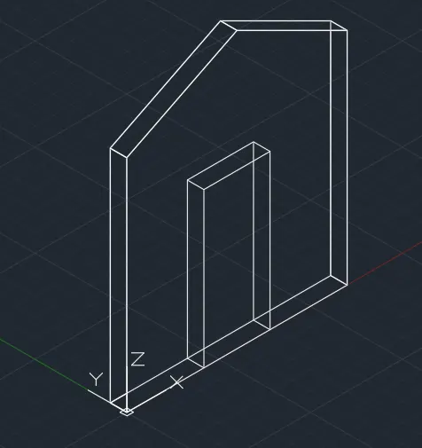
Creating various 3D Models like Furniture, Footing, Girder, Column drop with panel and Gable Wall in AutoCad
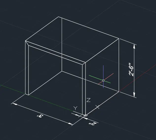
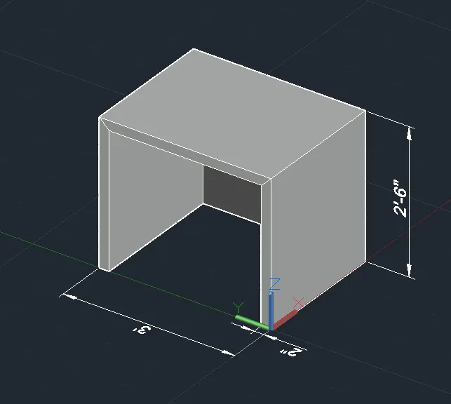
1.Aim: To Create 3D furniture elements using AutoCAD software.
Procedure:
- Open AutoCAD and click 3D modelling.
- In the command box type units-engineering-inches-0'-0"
- In the command box type limits-0'-0'
- In the command box type zoom
- In the command box type box and give the dimensions 3' and 2'-6"
- In the command box type plan
- In the command box type rec in the plan space
- In the command box type extrude in -Z axis
- In the command box type region and select the object
- Go to the shaded view.
- Go to command box and type dimension.
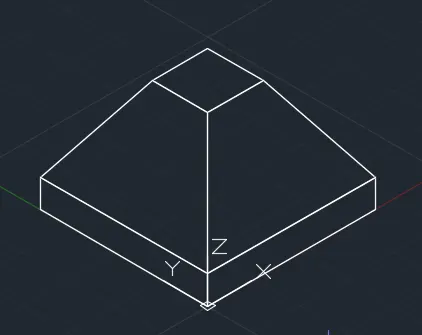
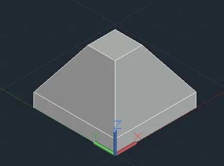
2. Aim: To create the 3D model of an isolated footing.
Procedure:
- Open AutoCAD and click 3D modelling.
- In the command box type units-engineering-inches-0'-0"
- In the command box type limits-0'-0'
- In the command box type zoom-a
- In the command box type rec and dimensions are 2'x2'
- In the command box type rec and dimensions are 1'x1'
- In the command box type move the 2nd rec at center od 1st rectangle.
- In the command box type move the rec to the z-axis of length 2'
- In the command box type extrude the 1st angle to downwards of 6"
- In the command box type region and select object
- In the command box type shaded
- In the command box type dimensions
- In the command box type 3dface to get the surface
RESULT-
3. Aim: To create the 3D view of the AASTHO type girder.
Procedure:
- Open AutoCAD and click 3D modelling.
- In the command box type limits-0'-0'
- In the command box type zoom-a
- In the command box type l to draw the desired lines at sw view.
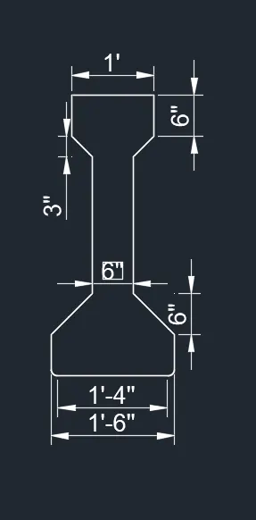
- In the command box type l and draw the line of distance 1'-6",6".1-6",6" and 1"
- In the command box type region
- In the command box type l and draw the line
- In the command box type sweep and select object and select the line.
- In the command box type shaded
- In the command box type dimensions
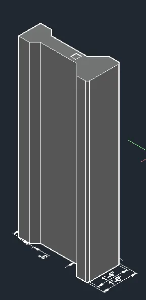
Result:
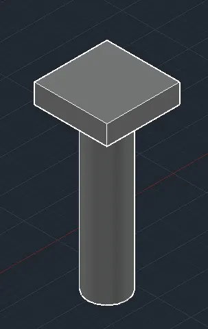
4. Aim: To create 3D model of a drop column with panel.
Procedure:
- Open AutoCAD-3D modelling.
- In the command box type units-engineering-inches-0'-0"
- In the command box type limits-0'-0'
- In the command box type zoom-a
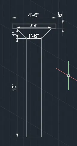
- In the command box type l to draw the desired lines of distance 10',1'-6",6",3'-6",4'-6"
- In the command box type circle
- In the command box type extrude of 10'
- In the command box type rec at the center of circle
- In the command box type extrude the rectangle.
- In the command box type region and select total object.
- In the command box type 3dorbit for the 3d view.
- In the command box type dimensions
Result:
5. Aim: To create the 3D model of a wall using Autocad
Procedure:
- Open AutoCAD and click 3D modelling.
- In the command box type units-engineering-inches-0'-0"
- In the command box type limits-0'-0'
- In the command box type zoom-a
- In the command box type line
- specify the point or select a point.
- Press f5 (isodraft) to get the line in desired direction
- keeping the isodraft in left direction one side wall is drawn
- Changing the isodraft in the other direction the next side of the wall is drawn
- In the command box type the required distance
Result: