Creating various 3D Models like Furniture, Footing, Girder, Column drop with panel and Gable Wall in AutoCad
AIM: Create a 3D Furniture element as shown in the Figure.
INTRODUCTION: Create a 3D Furniture element as shown in the Figure. Assume dimensions that are missing.
PROCEDURE:
- Open the cad and choose 3d modeling plane,
- by using box command created the box,
- later by using the hide command hide the face portion which is required,
- while creating the box the heights are given as per the drawing.
- dimensions are created by using the dim command.
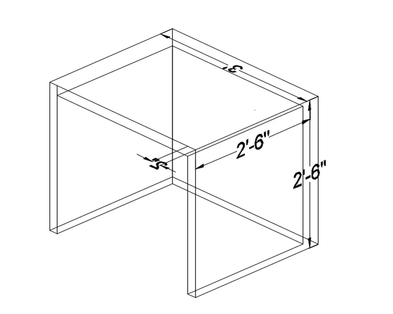
RESULT: Created a 3D Furniture element as shown in the Figure.
AIM: Create the 3d Model of an Isolated footing as shown in Figure.
INTRODUCTION: Create the 3d Model of an Isolated footing as shown in Figure, by using loft command.
PROCEDURE:
- choose the loft command from the menu bar,
- select the base point to choose the width of the rectangle is 4',
- choose the top radius from the command box choose the top box dimensions as 1',
- choose the height from the command box enter the 2',
- later using extrude option, select the bottom rectangle and select it to extrude 6" from the base.
- dimensions are created by using the dim command.
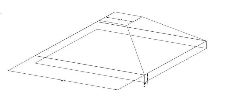
RESULT: Created the 3d Model of an Isolated footing as shown in Figure.
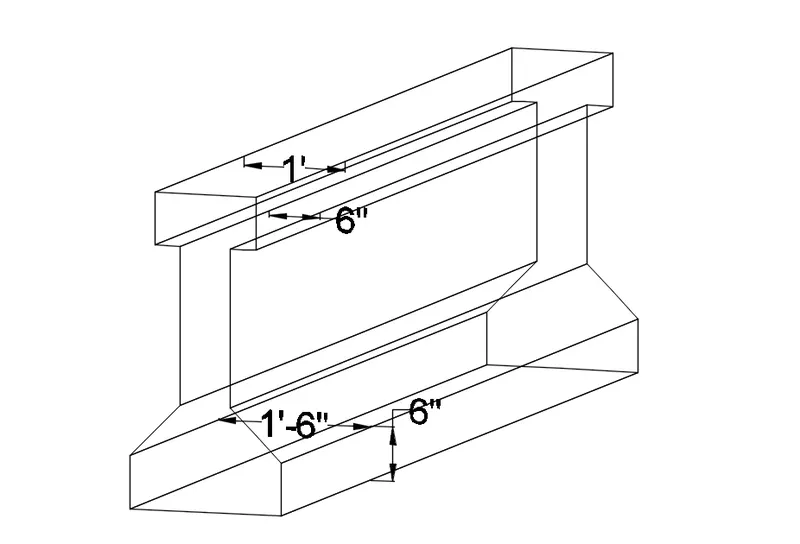
AIM: Create the 3D view of the AASTHO Type Girder.
INTRODUCTION: Create the 3D view of the AASTHO Type Girder. using the line command.
PROCEDURE:
- by using the line command, created the line face of the gider like base is 1'6",
- height of thickness is 6" in bottom,
- shaft height is 2' from the chamfer height,
- the top box is created with a width of 1' and 6" height.
- by using extrude command the entire 2d face is extruded with 10' length,
- dimentions are created by using dim linear command.
 the
the
RESULT: Created the 3D view of the AASTHO Type Girder.
AIM: Create a 3d Model of a drop column with the panel as shown in section and isometric view.
INTRODUCTION: Create a 3d Model of a drop column with panel as shown in section and isometric view. by uisng cylinder command, box command,
PROCEDURE:
- select the cylinder command create the cylinder with 1" diameter,
- with the 5' height entered in command box,
- later by using box command created a box with 6" thickness, and placed it in top of cylinder by using align command,
- second diagram by using the line command whole element creadted by using drawing units.
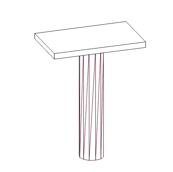
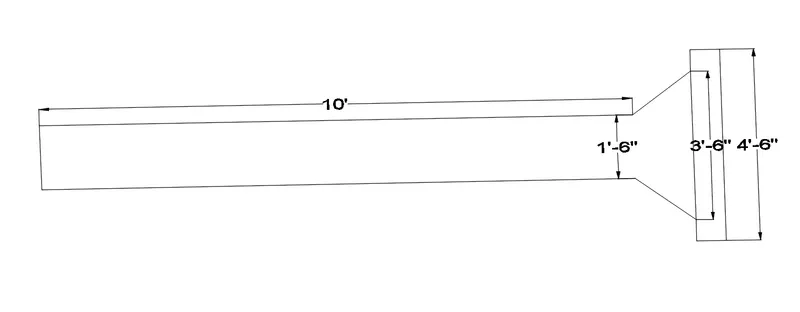
RESULT: Created a 3d Model of a drop column with the panel as shown in section and isometric view.
AIM: Create the 3d model of a wall as shown in Figure. Consider wall thickness as 9”.
INTRODUCTION: Create the 3d model of a wall as shown in Figure. Consider wall thickness as 9”.
PROCEDURE:
- by using ucs command chhose the ucs in custamized directions of x and y.
- sketch the line upto 10' with width of 10' ,
- create the height of slope from 10' to 12'6" by using line,
- in inside create a door by using line command with 7' height 3' width,
- by using extrude command extrude the all walls 9".
- dimentions are measured by dim linear.
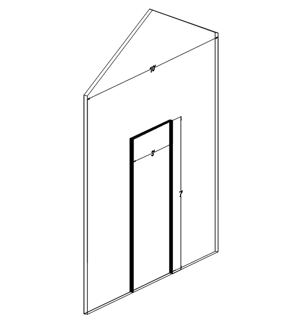
RESULT: Created the 3d model of a wall as shown in Figure. Consider wall thickness as 9”.