Creating various 3D Models like Furniture, Footing, Girder, Column drop with panel and Gable Wall in AutoCad
AIM: To create 3D model and view of
- FURNITURE ELEMENT
- ISOLATED FOOTING
- AASHTO TYPE GIRDER
- DROP OLUMN WITH PANEL
- WALL
COMMANDS:
- UNITS
- LIMITS
- LINE
- PLINE
- RECTANGLE
- OFFSET
- COPY
- MOVE
- SUBTRACT
- EXTRUDE
- REGION
- UCS
- BOX
- UNION
- BOUNDARY
- 3D ORBIT
- LOFT
- CONE
- MIRROR
PROCEDURE:
Open the AutoCAD file, change the settings to 3D modelling. Set the appropriate limits and units to feet and inches
1) 3D DRAWING OF FURNITURE ELEMENT
AIM: To create a 3D model of the funiture element
PROCEDURE:
- Open new autocad file, set the unit as feet and inches
- Create the appropriate layers for working on it
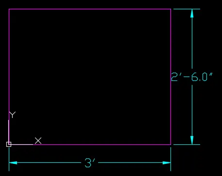
- Select the box from the tool bar, create it of length 3' and width as 2'6" and height 2'6" in top view
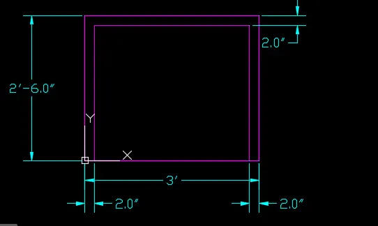
- Draw a line 2" from the right side and the front view
- Command rectangle and draw it as dimension of 32" and 2'4"
- Move the rectangle
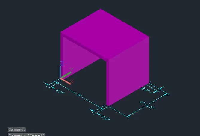
- Extrude the rectangle in Z axis of 2'4"
- Dimensions are given by dimlinear
RESULT: Created the 3D model of the funiture element
2) 3D MODEL OF ISOLATED FOOTING
AIM: To create a 3D model of isolated footing
PROCEDURE:
- Open new autocad file, set the unit as feet and inches
- Create the appropriate layers for working on it
- Command rectangle of 2'x2' on the top view. Offset inward 6"
- Command 3dorbit to view the suitable position
- Command move command small rectangle of 1'x1' by 2' in Z direction ortho on
- Command loft toolbar and select the two rectangles to loft
- Go to the top view and create rectangle of same size
- Extrude height as 6 and the direction of extrusion is pointed by mouse
- Give dimension
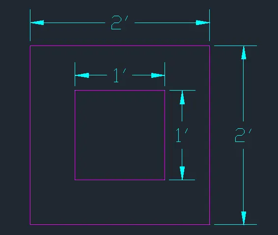
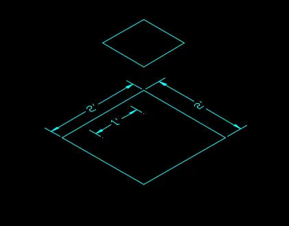
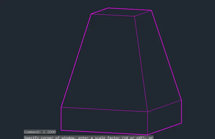
RESULT: Created the 3D model of isolated footing

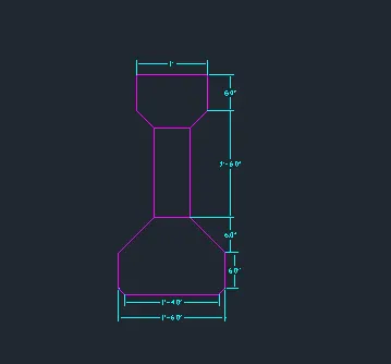
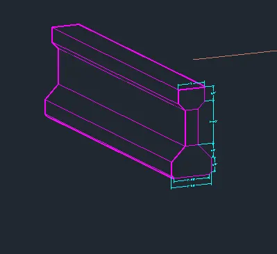
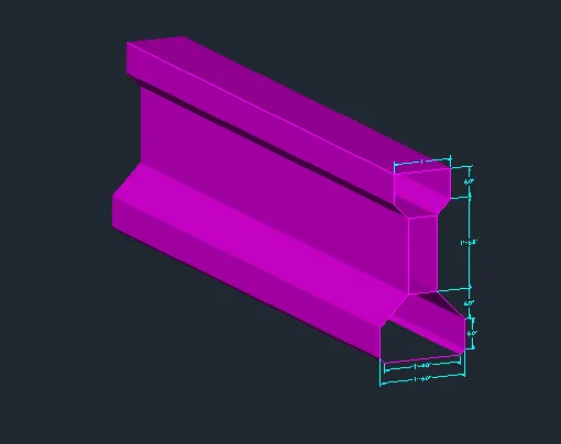
3) 3D MODEL OF AASTHO TYPE GIRDER
AIM: To create a 3D model of AASTHO type girder using AutoCAD
PROCEDURE:
- Open new autocad file, set the unit as feet and inches
- Create the appropriate layers for working on it
- Front view, Use UCS command, X and Y axis in the front view plane
- command line draw the I section with the given dimension. Command L draw the line 1' that is the top width of the girder
- Command L draw 6' downwards
- Give a taper distance and join web and flange Mirror the same on the other side
- Web is given a height of 1'6" from the end of tapering of flange portion
- Extend the web of the offset line. Again offset 6" from last line and taper the sides
- Draw the line of 10' in z direction
- Command sweep select the section and then the path through which the section to be swept
- Give the dimension
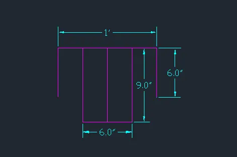
RESULT: Created the 3D model of AASTHO girder
4) 3D MODEL OF DROP COLUMN WITH PANEL
AIM: To create a 3D model of a drop column with panel section and its isometric view
PROCEDURE:
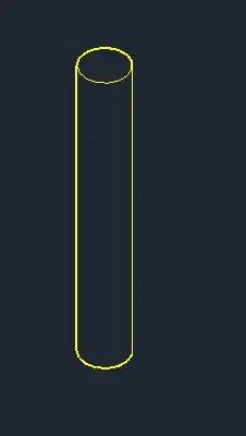
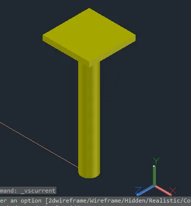
- Command circle and draw it of diameter 1'6" in top view
- Command region and select the circle
- Extrude it with a distance of 10'
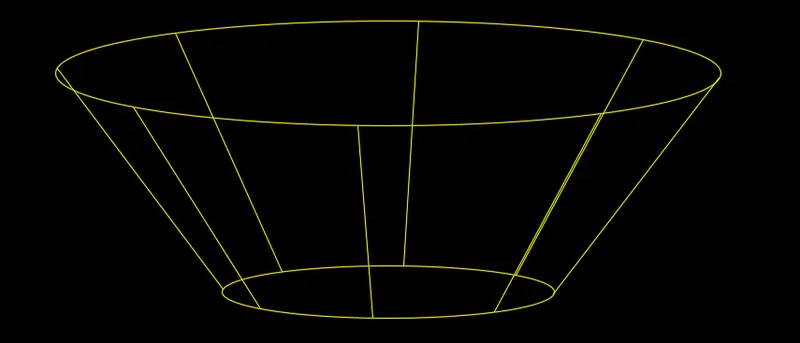
- Create a cone by clicking on cone from the home toolbar, click the diamter and dase diamter as 1'6"
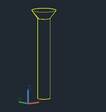
- Frustum of the cone is to be placed on the top of the extruded circle
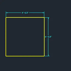
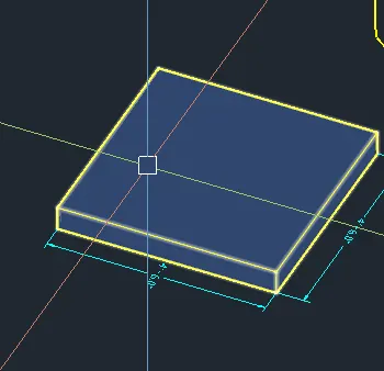
- In top view create the rectangle of dimension 4'6" x 4'6". Extrude it to a height of 6"
- Place the rectangle at the centre of cone in the top view and also adjust in the front view
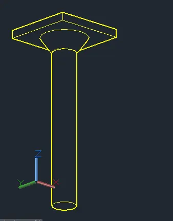
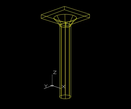
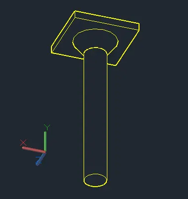
RESULT: Created the 3D model of drop column with panel
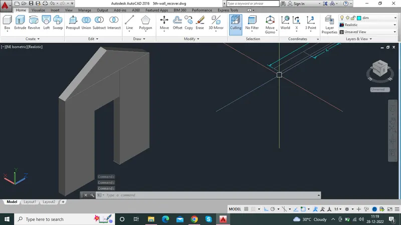
5) 3D MODEL OF WALL
AIM: To create a 3D model of AASTHO type girder using AutoCAD
PROCEDURE:
- Open new autocad file, set the unit as feet and inches
- Create the appropriate layers for working on it
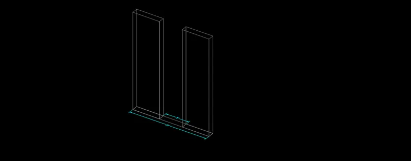
- Command the rectangle of 10'x9"
- Draw a line in the centre and offset 1.5' on both sides for the door opening
- Command Boundary and pickpoint to select the region
- Extrude the region to a height of 12'6" total height
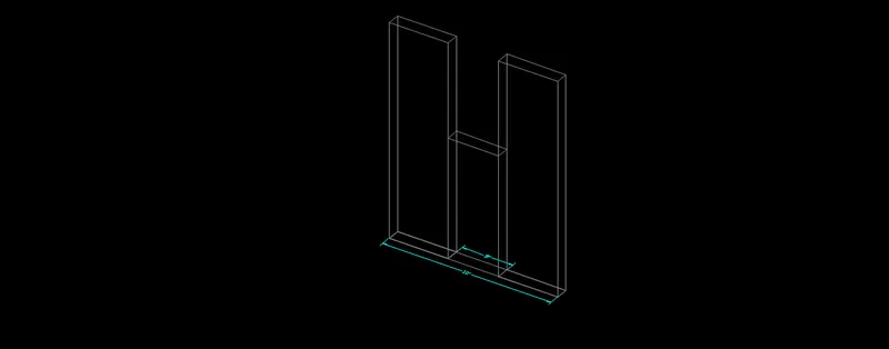
- Create rectangle in the place of door in the top view. Move the rectangle in Z axis at a height of 7' from the bottom
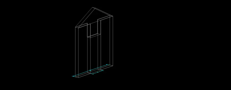
- Select front view and draw a line from the center of the moved line of door. Draw slanting line as the reference figure
- Mirror the line to the other side
- Create the region after converted it into polyline
- Extrude the regions
- Command union
- Give the dimension

RESULT: Created the 3D model of wall