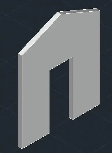
Creating various 3D Models like Furniture, Footing, Girder, Column drop with panel and Gable Wall in AutoCad
1. Create a 3D Furniture element as shown in the Figure. Assume dimensions which are missing.
Aim ,
To create a 3D Furniture element as shown in the Figure.
Procedure ,
* First set the units and limits as per required.
* Then set the view of the autocad to the 3d custom view.
* Draw the shape with given measurements.
* Use the command "Extrude" to elevate the shape drawn.
* Use "Shades of grey view " to enhance the diagram.
Diagram ,
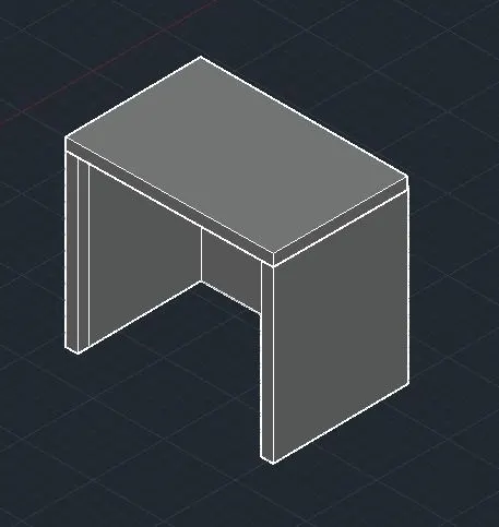
2. Create the 3d Model of an Isolated footing as shown in Figure.
Aim ,
To create the 3d Model of an Isolated footing as shown in Figure.
Procedure ,
* First set the units and limits as per required.
* Then set the view of the autocad to the 3d custom view.
* Draw the shape with given measurements.
* Use the command "Extrude" to elevate the shape drawn.
* Extrude using " Taper angle" option.
* Use "Shades of grey view " to enhance the diagram.
Diagram ,
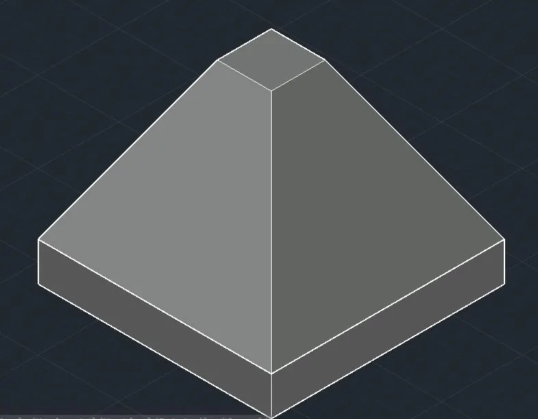
3. Create the 3D view of the AASTHO Type Girder.
Aim ,
To create the 3D view of the AASTHO type Girder.
Procedure ,
* First set the units and limits as per required.
* Then set the view of the autocad to the 3d custom view.
* Draw the AASTHO grider with given measurements.
* Use the command "Extrude" to elevate the shape drawn.
* Use "Shades of grey view " to enhance the diagram.
Diagram ,
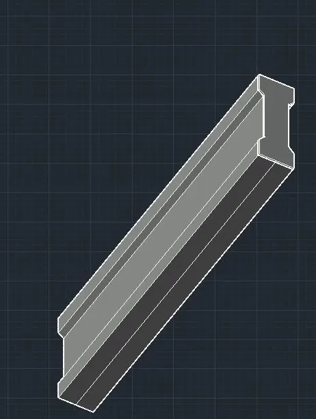
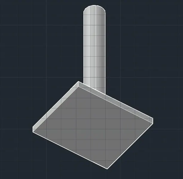
4. Create a 3d Model of a drop column with panel as shown in section and isometric view.
Aim ,
To create a 3d Model of a drop column with panel.
Procedure ,
* First set the units and limits as per required.
* Then set the view of the autocad to the 3d custom view.
* Draw the with given measurements.
* Use the command "Extrude" to elevate the shape drawn.
* Make the circle and sweep it using "sweep" option.
* Use "Shades of grey view " to enhance the diagram.
Diagram ,
5. Create the 3d model of a wall as shown in Figure. Consider wall thickness as 9”.
Aim ,
To create the 3d model of a wall as shown in Figure. Consider wall thickness as 9”.
Procedure ,
* First set the units and limits as per required.
* Then set the view of the autocad to the 3d custom view.
* Draw the shape with given measurements.
* Use the command "Extrude" to elevate the shape drawn.
Diagram ,